BLDC Phase Line Meter, a question of how to?

Tom on 101

100 mW
Joined
Jun 17, 2016
Messages
45
Location
Aptos, California
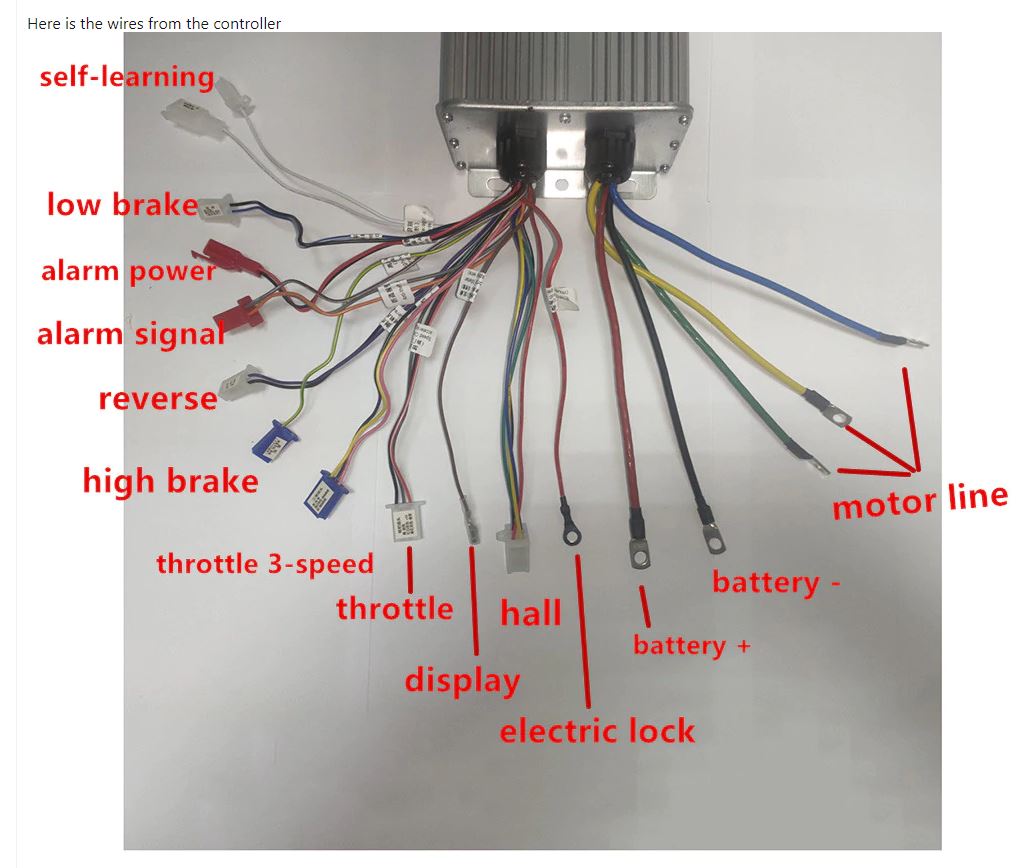
I recently swapped out my controller from a simple ebike controller to an ASI Bac4000. The controller is great and really smooth. But by swapping I lost some features from my old controller, the speedo and a Phase line Meter? This feature showed realtime current when throttling and realtime regen when off throttle, seen through a dash display. It's hard to find any information on how this feature worked or how to recreate the signal. It is a single line connection to the harness up to the dashboard for both speedometer and current monitoring if I'm right. So my dash harness has a voltmeter that can handle 84 volts. My issue is that I don't understand what the previous controller was sending through this signal line. surely not the full voltage?? Is there a shunting system which would help me with this? This line also seems to be the only speedometer line as well which is very confusing? The controller manual only has this line of info.

"Real-time battery current monitoring system make sure the output current will not
excess the maximum battery working current"

Make sense, don't want to fry the voltmeter embedded in the dash. But what kind of signal does the dash expect?

AND in the connector description, they call it a speedometer so there must be a dual function??

PhaseLineMeterConn.jpg

Thank you for reading this lamentful post and any help would be appreciated.

72 volt 80 Ah battery
Old controller was a YUYANG KING series high-power BLDC motor controller
New controller is an Bac4000
 
Tom on 101 said:
Phase line Meter? This feature showed realtime current when throttling and realtime regen when off throttle, seen through a dash display. It's hard to find any information on how this feature worked or how to recreate the signal.
Are you looking for battery current, or phase current? If the former, any wattmeter including the Cycle Analyst will show you that. The CA can also show you speed, if connected to a sensor measuring wheel speed or a hall sensor in a hubmotor. (dont' recommend the latter due to potential for damage if you ever have a phase/hall short).

If phase current, the controller will know that if it has phase current sensors (like any FOC controller will have). If it has a display, it might be possible to show that by a change in it's setup software (if you have access to that). Some of the ASIs can actually "talk to" certain LCDs that are fairly common; you'd need to contact ASI or go to the ASI site to find out which ones if that info is not in your manual, along with whether or not it can display phase current there (or only in the setup software, which it probably can).

It is a single line connection to the harness up to the dashboard for both speedometer and current monitoring if I'm right. So my dash harness has a voltmeter that can handle 84 volts. My issue is that I don't understand what the previous controller was sending through this signal line. surely not the full voltage??
That's easy to find out, by opening up your old controller and tracing where that wire went. If it is like one of the generic scooter types I have here, it's literally just a wire connected to one of the motor phases. (but you need to know before doing that, or you may destroy your display, and potentially the controller).

If it *is* just a motor phase wire connection, then it can be used to detect speed in a *hubmotor* as long as the dash knows how many magnets / poles are in the motor, because the AC signal from the controller phase output will change (commutation) frequency based on how fast the wheel is spinning, and there is an induced voltage back on it even when the controller is not powering the motor but wheel is spinning, so it still works.

How it detects current that way, I don't know--all it gets is a voltage, not a current, so it must be estimating the current based on known system (motor, controller, battery) settings already programmed into it at the factory. Whether those will be the same with any replacement parts, I don't know, so it might not be accurate anymore with parts changed out. You'd have to test that by comparing old parts to new parts under the same conditions.
 
amberwolf said:
Are you looking for battery current, or phase current? If the former, any wattmeter including the Cycle Analyst will show you that. The CA can also show you speed, if connected to a sensor measuring wheel speed or a hall sensor in a hubmotor. (dont' recommend the latter due to potential for damage if you ever have a phase/hall short).

If phase current, the controller will know that if it has phase current sensors (like any FOC controller will have). If it has a display, it might be possible to show that by a change in it's setup software (if you have access to that). Some of the ASIs can actually "talk to" certain LCDs that are fairly common; you'd need to contact ASI or go to the ASI site to find out which ones if that info is not in your manual, along with whether or not it can display phase current there (or only in the setup software, which it probably can).

That's easy to find out, by opening up your old controller and tracing where that wire went. If it is like one of the generic scooter types I have here, it's literally just a wire connected to one of the motor phases. (but you need to know before doing that, or you may destroy your display, and potentially the controller).

Thank you Amberwolf, yes it is the phase current I'm after and I'm following through with your advice, unfortunately this wire follows a path to this part on the old controller board to pin 28 & 28. So it must be a processed signal? Somehow this old controller was able to get speed and phase. I'm discovering the pinout now with continuity as the adjacent pins are part of the original harness and well marked. I'm going through what ASI signal wiring can carry but I dont see anything there to create an output like this, even though I'm sure Bacdoor can monitor phase amps very well. Its a pretty cool feature how they did it cause it was monitoring my speed and phase current (even off throttle regen) all from one signal line. My display is pretty premative otherwise, no buttons, no configuration.
display.jpg

Pin 28 = Phase Meter Line
Pin 25 = 0

Pin 28= Phase Meter Line plus Anti-theft Sensor
PIn 4 = Anti-theft
Pin 18 = Power switch (key lock)

1.jpg2.jpg3.jpg

amberwolf said:
How it detects current that way, I don't know--all it gets is a voltage, not a current, so it must be estimating the current based on known system (motor, controller, battery) settings already programmed into it at the factory. Whether those will be the same with any replacement parts, I don't know, so it might not be accurate anymore with parts changed out. You'd have to test that by comparing old parts to new parts under the same conditions.

https://www.aliexpress.com/i/33038531211.html?spm=2114.12057483.0.0.5c3068fcpqVDhi
After searching a while I found the display and a rough explanation of how to hook it up, it looks like i can hook up a phase wire directly but it is kinda scary!! Also i could use a hall signal but will need to take my dash apart to find the connection.
 
Tom on 101 said:
Thank you Amberwolf, yes it is the phase current I'm after and I'm following through with your advice, unfortunately this wire follows a path to this part on the old controller board to pin 28 & 28.
I don't see any traces on the bottom that go from where the pad marked 28 (either of them) connect to each other, to any other part or place on the board, so that trace must be on the top of the board. <snip>
I'm discovering the pinout now with continuity as the adjacent pins are part of the original harness and well marked
The first point I would measure is from either pad 28 to each of the phase wires, one at a time. If you get essentially zero ohms to one of htem, then that's what it is. :)

It's possible it could also go thru a diode, which would be easy to implement on your new system.


I'm going through what ASI signal wiring can carry but I dont see anything there to create an output like this,
It's not designed to work the same way, so you won't likely find the same kind of signal marked on it (plus it's probably not marked in poorly-translated Chinese. ;) ).

even though I'm sure Bacdoor can monitor phase amps very well. Its a pretty cool feature how they did it cause it was monitoring my speed and phase current (even off throttle regen) all from one signal line.
Which is why it makes sense for it to be a simple phase wire connection. (though again, dunno how they could measure current that way--they could only measure voltage, and then *estimate* current).
 
amberwolf said:
The first point I would measure is from either pad 28 to each of the phase wires, one at a time. If you get essentially zero ohms to one of htem, then that's what it is. :)

It's possible it could also go thru a diode, which would be easy to implement on your new system.

Pin 28 to Green phase wire is 37.44 ohm
Pin 28 to Yellow phase wire is 37.40 ohm
Pin 28 to Blue phase wire is 100.00 ohm

I see some diode group near Pin28 on top of the board but they are very small there was resistance between 28 and one of the SMT resistors.
 
Tom on 101 said:
Pin 28 to Green phase wire is 37.44 ohm
Pin 28 to Yellow phase wire is 37.40 ohm
Pin 28 to Blue phase wire is 100.00 ohm

I see some diode group near Pin28 on top of the board but they are very small there was resistance between 28 and one of the SMT resistors.
Mesure that 28 to blue with the red and black meter wires swapped. If the reading is different, it's probably thru a diode. (especially if 28 to y or g is still 37).
 
amberwolf said:
Mesure that 28 to blue with the red and black meter wires swapped. If the reading is different, it's probably thru a diode. (especially if 28 to y or g is still 37).

With wire reversed the very same readings.
Pin 28 to Green phase wire is 37.43 ohm
Pin 28 to Yellow phase wire is 37.41 ohm
Pin 28 to Blue phase wire is 99.80 ohm

Am I right in thinking this would indicate some kind of current restriction but that the display is monitoring the voltage flux or some delta but is the real voltage not signal produce from within the controller? Interestingly the display claims monitoring over this one line can be either/or for hall wire or this phase line?
 
Tom on 101 said:
With wire reversed the very same readings.
Pin 28 to Green phase wire is 37.43 ohm
Pin 28 to Yellow phase wire is 37.41 ohm
Pin 28 to Blue phase wire is 99.80 ohm

Am I right in thinking this would indicate some kind of current restriction but that the display is monitoring the voltage flux or some delta but is the real voltage not signal produce from within the controller?
It's probably a simple resistor, then. But I am not sure why it measures lower thru the other two phases than it does thru that one (presumably the controller is disconnected from everything, including hte motor, when doing these measurements?).

I would have to guess that the resistor in question will probably be marked as "101" if it's a little black rectangle surface mount. If it's a tubular type with wires down to the board, it probably has stripes with brown black brown and probably gold. These would be 100ohm resistors. It is probably right there at the pad 28 area, and you should read basically zero ohms from the pad to one end of the resistor, and basically zero ohms from the other end of the resistor to the blue phase, if so.

The resistor is probalby not there to protect the display, but rather to protect the *controller* in the case of someone not connecting that wire and it's tip shorting to something else, so it doesn't blow the FETs. And so you could probably directly connect a wire from the display's input for this right to any one of the phase wires on the new controller, right at it's output, or where it connects to a motor phase wire. Using a similar 100ohm (most likely--you should verify that's what it is) resistor at the connection point is probably a safe thing to do, in case of a wire insulation break/short to something else, to protect the ASI controller. You can probably use higher resistances if you like; I don't know what difference, if any, it would make. (that's an experiment you'd want to conduct with the original controller, since you already know what readings you get from it under various conditions, and so would know if it was different with a bigger resistor in series with the controller-to-display connector).

But in any case, yes, it is reading the "real" or "direct" phase signal, rather than a processed one, since it does connect to the phase wires with such a low resistance. If there were basically infinite resistance to the phases, it would probably mean it went to the MCU for some signal output.

Interestingly the display claims monitoring over this one line can be either/or for hall wire or this phase line?
It could do speed monitoring on a hall wire, but not current or voltage. There is probably a jumper inside the display to select which type of wire is used to monitor from, if it requires any changes. There's a thread around here somewhere that shows the inside of some speedo display with different pads for various functions, I think it was by MSJPhoto1956 (might have the first few letters mixed up).
 
Apparently it's MJSfoto1956 :oops: and I think this is the post
https://endless-sphere.com/forums/viewtopic.php?f=14&t=98446&p=1499872&hilit=speed%2A#p1499401
where the pic shows an SD pad with a wire on it and a YXT pad with no wire. FOr that specific unit, to use a phase wire it'd go to the SD pad, to use a hall wire it'd go to the YXT pad, but only one of them can be used at a time (can't connect to both). I'm sure this is not the same display you have, but it's likely the function access is similar.


Personally I don't like using any device that has to monitor a hall wire from the motor, because if anything ever happens that shorts the hall wire to a higher voltage (like a motor axle wire failure, etc), it'll probably destroy the monitoring device's input from the high phase voltage. (something like this happened to my first Cycle Analyst v3, destroying the MCU and probably other parts). So I prefer to use a separate speed sensor with a magnet on the wheel annd sensor on the frame.

Never had a speedo that could use the phase wire itself, so dunno how I'd feel about that. :)
 
amberwolf said:
I would have to guess that the resistor in question will probably be marked as "101" if it's a little black rectangle surface mount. If it's a tubular type with wires down to the board, it probably has stripes with brown black brown and probably gold. These would be 100ohm resistors. It is probably right there at the pad 28 area, and you should read basically zero ohms from the pad to one end of the resistor, and basically zero ohms from the other end of the resistor to the blue phase, if so.
Tubular and gold/copper in color, brown wire is on pin 28.
Resistor.pin28.jpg
amberwolf said:
The resistor is probalby not there to protect the display, but rather to protect the *controller* in the case of someone not connecting that wire and it's tip shorting to something else, so it doesn't blow the FETs. And so you could probably directly connect a wire from the display's input for this right to any one of the phase wires on the new controller, right at it's output, or where it connects to a motor phase wire. Using a similar 100ohm (most likely--you should verify that's what it is) resistor at the connection point is probably a safe thing to do, in case of a wire insulation break/short to something else, to protect the ASI controller.
Ok I'll try to identify the resistor and add it inline with the Phase Meter Line. By the way the little bullet connector comes in a thick insulator so I think you right about the worry of a short, it all make sense. Tiny little resistor.
amberwolf said:
You can probably use higher resistances if you like; I don't know what difference, if any, it would make. (that's an experiment you'd want to conduct with the original controller, since you already know what readings you get from it under various conditions, and so would know if it was different with a bigger resistor in series with the controller-to-display connector).
Not to clear on this part but I'll look into hooking up the original controller safely and make some measurements.

amberwolf said:
But in any case, yes, it is reading the "real" or "direct" phase signal, rather than a processed one, since it does connect to the phase wires with such a low resistance. If there were basically infinite resistance to the phases, it would probably mean it went to the MCU for some signal output.
Great, very educational and a tool for later. Thank you! :thumb:
 
Tom on 101 said:
Tubular and gold/copper in color, brown wire is on pin 28.
Resistor.pin28.jpg
THe large tubular thing with reddish bits inside is a diode (very likely a 1n4148 or similar, but could be a zener, which is used for voltage limiting). The banded end is the "cathode" or "negative" end, and which way that points in a circuit depends on what it's being used for. I can't see the traces on the board to know waht the circuit is there, so you would have ot measure them and draw them out on paper. (that gets time consuming and a little complicated sometimes).

The little black things near it are resistors. What are the numbers printed on them?


BTW, if you want to test the whole idea without risk to the controller, and probalby none to the display, leave the controlelr disconnected from the system entirely, and just wire any one motor phase wire to the display's wire, and make sure the display has whatever other stuff it needs to operate.

Roll the bike around under just your power, or lift the wheel off ground and spin it by hand (or by friction wtih another motor wheel on another bike, slowly).

If all the assumptions are correct ;) then you should read at least speed on the display.
 
amberwolf said:
The little black things near it are resistors. What are the numbers printed on them?

I can get those numbers.

The one closes to R40 is 5102.
The one above is 4991

The data sheets on the 1n4148 and Zener seem similar, they restrict voltage direction, if I'm reading this right? But I'm not able to fully understand the use in a circuit other that as a reverse polarity protection or as a step down similar to a bucky.
amberwolf said:
BTW, if you want to test the whole idea without risk to the controller, and probalby none to the display, leave the controlelr disconnected from the system entirely, and just wire any one motor phase wire to the display's wire, and make sure the display has whatever other stuff it needs to operate.

Roll the bike around under just your power, or lift the wheel off ground and spin it by hand (or by friction wtih another motor wheel on another bike, slowly).

If all the assumptions are correct ;) then you should read at least speed on the display.

Ok hook up the harness without the controller...Sounds very informative I'll give this a try.
 
Tom on 101 said:
The one closes to R40 is 5102.
The one above is 4991
Then those are 51 kΩ and 4.99 kΩ, respectively. That means that neither one of those is in series with that wire to the phases. The diode isn't either, or else you wouldn't get the same resistance both directions.

So the part that is in series with that wire to the phases is somewhere else on the board (probably at or near the phase wire it goes to, but could be anywhere). This means that if you want to explore the actual circuit used more fully, you' would have to start drawing up where the actual traces go from those "28" pads to wherever else they go on the board.


The data sheets on the 1n4148 and Zener seem similar, they restrict voltage direction, if I'm reading this right? But I'm not able to fully understand the use in a circuit other that as a reverse polarity protection or as a step down similar to a bucky.
They are *similar*, but not usually used the same way. A regular diode is usually used to block current in one direction but allow it in the other. A zener is usually used with a resistor as a kind of voltage regulator or voltage limiter; it literally just wastes all the power above a certain voltage as heat within itself and the series resistor used. If you're interested in learning electronics like this stuff, this is a good site to start with, from the beginning:
https://www.allaboutcircuits.com/textbook/
 
amberwolf said:
Tom on 101 said:
The one closes to R40 is 5102.
The one above is 4991
Then those are 51 kΩ and 4.99 kΩ, respectively. That means that neither one of those is in series with that wire to the phases. The diode isn't either, or else you wouldn't get the same resistance both directions.

So the part that is in series with that wire to the phases is somewhere else on the board (probably at or near the phase wire it goes to, but could be anywhere). This means that if you want to explore the actual circuit used more fully, you' would have to start drawing up where the actual traces go from those "28" pads to wherever else they go on the board.

Make sense so more exploration but I'm now set up to run the test on the phase line to see if I can read speed. I'll report back what I find. The instruction for these units do say connect directly to the phase line, its very intesting. when ordering one needs to specify voltage maybe that s clue to how they pre-configure them.

amberwolf said:
BTW, if you want to test the whole idea without risk to the controller, and probalby none to the display, leave the controlelr disconnected from the system entirely, and just wire any one motor phase wire to the display's wire, and make sure the display has whatever other stuff it needs to operate.

Roll the bike around under just your power, or lift the wheel off ground and spin it by hand (or by friction wtih another motor wheel on another bike, slowly).

If all the assumptions are correct ;) then you should read at least speed on the display.

Trying the above didn't produce any speedometer reading, I even drove the wheel with another bike spinning it up pretty good. I then got enough nerve to hook it up to to one of the phase poles on my controller, turning on the whole system didn't fry the dash (phew)! What it shows on display was a full throttle animation at idle! and 59 kph and under throttle something like 79 kph and no change in the throttle animation. So it didn't work but was still interesting. The dash must be programmable in some fashion so off to find more out about that. At least I know i can hook it up once I figure what is needed.

Ok thank you for the resources, I feel like a learned a thing or two about how to investigate these harnesses better.
 
Dear Folks, I have a single wire for a display line. What display would work to be connected to this line.

Any Idea what to buy.
Does someone can make a proposal what to buy for display.

Greeting Bob

9aece42a932af5ad97653e14e6a2ea53.jpg


Gesendet von meinem CPH1911 mit Tapatalk

 
Back
Top