Adding hall sensors - Best positions?

sdobbie

100 W
Joined
Dec 14, 2013
Messages
137
Location
Fife Scotland
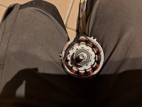
Hi everyone, today I got a BLDC motor out of a broken 36v cordless chainsaw and was wanting to add hall sensors to it so that I can test controllers properly. I was wondering what the best position for the sensors would be? I could epoxy them between the spaces between the windings (shown in red) Or space them differently so that one of them is embedded into the nylon coil former(shown in yellow) I could get more pictures of the rotor if that would help.

20210219_190432.png
 
As long as they are 120 electrical degrees apart it will work. Between the stator poles (red dots) is probably easiest.

Another way is to 3d print a ring that goes around the shaft and embed small magnets in the ring corresponding to the rotor magnet positions. Then you place your hall sensors externally close to the ring.
 
OP might need to be careful. It's usually between the windings but not always. For example I've got a12 slot 14 magnet motor (7pp) where the sensors are placed tighter than the slots.

I think that there are 2 arrangements that definitely work for all motors - 120 degree equal spacing on the whole motor (between slots will always work that way) and 120/no. pole pairs between the sensors.

Other arrangements can work but finding a nice between the slots layout isn't guaranteed.
3 sensors at 120 mechanical degrees
PXL_20210220_114637928.jpg

PXL_20210220_114412562.jpg

PXL_20210220_114325254.jpg

All 3 of these are definitely 120 electrical degrees.
 
Thanks for the examples.

I can't find any examples of hall placement on inrunner motors. Most of them seem to have encoders rather than hall sensors.

It seems common on the outrunners that they are arranged with two sensors on the poles and one in the slot and I have shown this layout on my inrunner here and will experiment with it later today hopefully.
Untitled2.png

My electric bike motor is a similar arrangement as the examples you posted but it is also an outrunner.

Untitled2a.png


I suppose I could give it a try and report my findings.
 
FWIW, this is a fairly common topic, and there is some existing potentially useful information you may wish to peruse.
https://endless-sphere.com/forums/search.php?keywords=add*+hall*&terms=all&author=&sc=1&sf=titleonly&sr=topics&sk=t&sd=d&st=0&ch=300&t=0&submit=Search
 
The problem is, you're treating the position of the halls as a function of the stator when it's not. It's a function of the rotor.

You need to work out how many pole pairs your rotor has, otherwise you're just blindly guessing.

Use a magnet and count, or stick a few amps on two of the phases and count the cogging steps.

Number of slots on stator is NOT the same as number of poles on rotor. They're kind of related but unless you reverse engineer the windings pattern you're unable to work out the pole arrangement.
 
mxlemming said:
The problem is, you're treating the position of the halls as a function of the stator when it's not. It's a function of the rotor.

You need to work out how many pole pairs your rotor has, otherwise you're just blindly guessing.

Use a magnet and count, or stick a few amps on two of the phases and count the cogging steps.

Number of slots on stator is NOT the same as number of poles on rotor. They're kind of related but unless you reverse engineer the windings pattern you're unable to work out the pole arrangement.

I opted for the few amps thrpugh the phases method and found 5 distinct positions where the rotor would settle. I also think it is delta wound and I would change this to star later.
 

Attachments

  • 20210224_192557.jpg
    20210224_192557.jpg
    529.5 KB · Views: 396
So you've got 5 pole pairs. Your obvious choices are:
120 degree equal
360/5/3=24 degrees apart

There's no nice combination for this. I'd go for the 120 degree spacing. That is, 3 empty slots between each hall sensor.
 
When you apply power to a pair of phase wires and let the rotor find it's spot, one hall sensor needs to be exactly half way between a pair of magnets (right at the trigger point for the hall). Use other phase wire combinations to find the other spots. If the rotor lines up so a pair of magnets is perfectly aligned with a pair of stator poles, then it can go in the gap. If it's off a little, it screws up the timing. It may work to place the hall sensors so they are facing the edge of the magnets instead of the faces. I think you need both bearings on to have the rotor move freely.
 
fechter said:
When you apply power to a pair of phase wires and let the rotor find it's spot, one hall sensor needs to be exactly half way between a pair of magnets (right at the trigger point for the hall). Use other phase wire combinations to find the other spots. If the rotor lines up so a pair of magnets is perfectly aligned with a pair of stator poles, then it can go in the gap. If it's off a little, it screws up the timing. It may work to place the hall sensors so they are facing the edge of the magnets instead of the faces. I think you need both bearings on to have the rotor move freely.

For most modern controllers, VESC, stancecoke, ST (nucular) and my code included, the absolute angle is not so important, the code accounts for it - for mine at least it makes not the slightest difference. It's only really an issue for super basic 6 step controllers.

It needs to have a decent approximation to 120 electrical degree separation though. If they're in all but random places, startup torque will be terrible/impossible.
 
Back
Top