magicmicros
1 µW
- Joined
- May 26, 2021
- Messages
- 2

I'm running a 3kW bike with a KT72V50A controller, but it's so-so.
I want to update, use a sinewave controller ( or better
") )
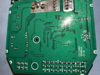
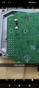
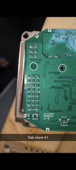
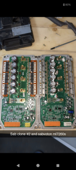
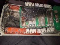
)So, I found this, what seems to be a ML7280 clone.
Price is good, about $65. And after looking inside, it's SO much better quality than the KT crap, which cost even more.
I've spent 3 days on reverse engineering it and now have complete schematics, in addition to a detailed knowlegde of the design.
It's un-named, but looks like the ML7280 (capabilities were similar, 72V, 80A).
Does anyone here have any experience with this?
I have a "real" ML7280 incoming, so I'll soon know if there's any differences.
Anyway, the plan is to write my own firmware for this.
First of all because it's totally undocumented but also to understand better how stuff works.
Documentation is here:
https://github.com/magicmicros/ml7280_clone
/J