Paired motor?

edgefx1

1 mW
Joined
Sep 22, 2020
Messages
16
so i remember reading that, i believe it was sinewave controllers, needs a paired motor to work correctly, my question is:

what does paired motor mean? or rather, HOW is it paired?

for context, i was rewinding a burnt out geared hub motor with 18 slots and 20 poles, the calculator gave me this winding pattern: AaABbBCcCAaABbBCcC, so i followed it to a T, then i plugged it into my dual mode controller (no p settings, just ignition) and gave it throttle, the motor locked up, BUT i discovered if i gave it a spin start with my hand and then throttle while it was spinning the motor would turn over just fine, i did not install hall sensors on the motor becuz i figured if it worked fine in sensorless mode then itll be fine later when i put in the sensors eventually. but now im curious as to why it needed that spin start, one thing i DONT know about the controller is if its sq wave or sinewave, its just a generic "36v 16a max jp-mfzj1173d1808222" i do know it works with or with out the halls plugged in. do these dual mode controllers switch between sine and square depending on sensors or sensorless mode? or are the sine OR sq regardless of the sensors?
 
edgefx1 said:
so i remember reading that, i believe it was sinewave controllers, needs a paired motor to work correctly, my question is:

what does paired motor mean? or rather, HOW is it paired?
I don't know what "paired" means, as I have not seen that term used in this context, but if you are using FOC controllers, and some other advanced types, you must program the controller with the various motor parameters, such as kV, inductance, resistance, hall advance/retard timing angle, etc. Some have autodetection routines that work well enough, some of them require significant manual tuning even after this is done.

What specific controller do you need to use, in what specific situation, for what feature / function set?


for context, i was rewinding a burnt out geared hub motor with 18 slots and 20 poles, the calculator gave me this winding pattern: AaABbBCcCAaABbBCcC, so i followed it to a T, then i plugged it into my dual mode controller (no p settings, just ignition) and gave it throttle, the motor locked up, BUT i discovered if i gave it a spin start with my hand and then throttle while it was spinning the motor would turn over just fine, i did not install hall sensors on the motor becuz i figured if it worked fine in sensorless mode then itll be fine later when i put in the sensors eventually. but now im curious as to why it needed that spin start,
If the controller is sensorless, but has a poor startup routine, or a "pedal start" requirement, then you'd have to start the motor moving in the correct direction every time for it to startup, and be unable to start on it's own.

If it's pedal-start or pedal-first, then even if it had hall sensors it would still require you to spin the motor first (because it's meant to never power the motor by itself, but only assist once the bike is already moving).

If the controller has neither issue, then it could have one phase that is not working--either miswound in the motor, or miswired, or faulty connection to the controller, or failed FETs in that controller phase. Some sensorless controllers can drive a motor with no load (off ground) even with a poorly-working or missing phase. Apply a load, and it won't work right, either being very rough or noisy, or just not work at all.

do these dual mode controllers switch between sine and square depending on sensors or sensorless mode? or are the sine OR sq regardless of the sensors?
That depends on the specific controller.

Some will be only one, or only the other.

Some will have a setting in their display to change them.

Some, like the older Grinfineon I have, are sine only in sensored mode; if the halls are not working or not connected/present, it falls back to trapezoid (square) mode.
 
amberwolf said:
edgefx1 said:
so i remember reading that, i believe it was sinewave controllers, needs a paired motor to work correctly, my question is:

what does paired motor mean? or rather, HOW is it paired?
I don't know what "paired" means, as I have not seen that term used in this context, but if you are using FOC controllers, and some other advanced types, you must program the controller with the various motor parameters, such as kV, inductance, resistance, hall advance/retard timing angle, etc. Some have autodetection routines that work well enough, some of them require significant manual tuning even after this is done.

What specific controller do you need to use, in what specific situation, for what feature / function set?


for context, i was rewinding a burnt out geared hub motor with 18 slots and 20 poles, the calculator gave me this winding pattern: AaABbBCcCAaABbBCcC, so i followed it to a T, then i plugged it into my dual mode controller (no p settings, just ignition) and gave it throttle, the motor locked up, BUT i discovered if i gave it a spin start with my hand and then throttle while it was spinning the motor would turn over just fine, i did not install hall sensors on the motor becuz i figured if it worked fine in sensorless mode then itll be fine later when i put in the sensors eventually. but now im curious as to why it needed that spin start,
If the controller is sensorless, but has a poor startup routine, or a "pedal start" requirement, then you'd have to start the motor moving in the correct direction every time for it to startup, and be unable to start on it's own.

If it's pedal-start or pedal-first, then even if it had hall sensors it would still require you to spin the motor first (because it's meant to never power the motor by itself, but only assist once the bike is already moving).

If the controller has neither issue, then it could have one phase that is not working--either miswound in the motor, or miswired, or faulty connection to the controller, or failed FETs in that controller phase. Some sensorless controllers can drive a motor with no load (off ground) even with a poorly-working or missing phase. Apply a load, and it won't work right, either being very rough or noisy, or just not work at all.

do these dual mode controllers switch between sine and square depending on sensors or sensorless mode? or are the sine OR sq regardless of the sensors?
That depends on the specific controller.

Some will be only one, or only the other.

Some will have a setting in their display to change them.

Some, like the older Grinfineon I have, are sine only in sensored mode; if the halls are not working or not connected/present, it falls back to trapezoid (square) mode.

i remember reading that some controllers need a paired motor to work, this is only for sinewave controllers, but i wasnt too sure what they meant by that, i thought maybe it was the winding pattern? but im really not sure since there was no more information beyond it being "paired" to the controller. im not looking to use any specific controllers, i was just hoping for some more insight to what they meant by paired motors was all.

the controller i was using to test my winding is not a kick start controller, its a simple ignition, and throttle to go, it can run with or without sensors, its basically the most generic type of controller there is.

ill check for phase shorting in the windings, might have nicked sumtin post winding.

thanks for the input!
 
edgefx1 said:
i remember reading that some controllers need a paired motor to work, this is only for sinewave controllers, but i wasnt too sure what they meant by that, i thought maybe it was the winding pattern? but im really not sure since there was no more information beyond it being "paired" to the controller. im not looking to use any specific controllers, i was just hoping for some more insight to what they meant by paired motors was all.

You'd need to link the specific places you read that, so we can see what they mean in context, for us to figure out what they meant.
 
amberwolf said:
edgefx1 said:
i remember reading that some controllers need a paired motor to work, this is only for sinewave controllers, but i wasnt too sure what they meant by that, i thought maybe it was the winding pattern? but im really not sure since there was no more information beyond it being "paired" to the controller. im not looking to use any specific controllers, i was just hoping for some more insight to what they meant by paired motors was all.

You'd need to link the specific places you read that, so we can see what they mean in context, for us to figure out what they meant.


https://scooter.guide/sinewave-vs-squarewave-controllers/

Thats one article in regards to what i mean, they only ever say it needs to be matched or paired, but don't really mention how or in what regards
 
Ah. I don't see the word "paired" anywhere in the page, but they do use the word "matched" here:
Disadvantages of Sine Wave E-scooter Controllers
Only compatible with matched motors
I don't know what specifically they're referring to, since they don't discuss this.

My best guess is that it refers to the BEMF waveform of the motor itself, whether it is a sine or trapezoidal waveform. To find out for any particular motor, you need an oscilloscope and a way to manually spin the motor continuously at a particular RPM without running it as a motor (because you want to see the voltage (or current, if you have an electrical load you can place on it) waveform produced by the motor, and not anything fed to it by a controller).

There are some discussions about this type of compatibility here on ES; I don't recall the specific conclusions, except that most common ebike/scooter/etc 3-phase BLDC motors seem to make a sufficiently sinusoidal waveform to work fine with either type of controller, and that there are some rare exceptions that just never run "right" on one or the other type of controller. I didn't find the specific threads for this in a couple-minute search, but they are most likely within the same Motor Technology subforum that this thread is in.


This post has images to compare the two BEMF waveforms
https://endless-sphere.com/forums/viewtopic.php?f=30&t=116326&p=1717179&hilit=sin%2A+trap%2A#p1717130

This one mentions that a sine BEMF motor is less electrically noisy than a trap BEMF motor (which should make it easier for the controller to drive cleanly, I think).
https://endless-sphere.com/forums/viewtopic.php?f=30&t=22232&p=323787&hilit=sin%2A+trap%2A#p323787


Note also that there are (at least) two kinds of sinewave controllers. The cheapest is just like a trap / square controller, except that it uses a lookup table with a sinewave pattern in it instead of trap, to create the motor drive waveforms. It doesn't do anything special, and doesn't need to know anything about the motor to work. "All" (perhaps their are exceptions I haven't seen) of the generic sinewave controllers, plus any combo sine/trap controllers (like those that fallback to trap if sine doesn't work or if halls fail, etc), do it this way. These don't monitor phase currents, just battery current, because they don't need to (the information isn't useful to the controlling process they use), so the waveforms they drive with are voltage waveforms, and their throttles only control the PWM of this waveform, essentially controlling motor speed by controlling average voltage on the motor. Most of these really suck at sensorless startup, or sometimes even low-speed sensorless operation. Most of them also don't support variable regen, just on/off.


The more advanced, more efficient, and "better" way is using FOC or some other variant of motor *current* control that monitors phase currents in the motor and modifies the waveform to drive them based on the results. These use the throttle to control the current to the motor, so they control the torque of the motor, not it's speed (though some of them have options to emulate the speed control instead). Given the right software in them, these can support great sensorless startup from a stop even under high loads, and variable regen braking--even non-regen braking can be done, variably, by forcing controlled reverse currents thru the phases to force the motor to slow down much quicker than a simple regen system can. Whether any particular controller like this does actually do these things well, or at all, depends on the software they run, and how well it is written. THe hardware in them, though, should allow it to be done (assuming sufficient MCU computing power). (this is why you may see OSFW (open source) projects to replace firmware on a popular controller that doesn't do these things with firmware that *does*).

The disadvantage of the more advanced controller to the average non-technical DIYer is that they require specific info about the motor to drive it correctly, and the more advanced the controller is with more options, the more things the user must setup *just right* to make the motor work correctly in their specific application. Some have good autotuning/learning routines; manual tweaking of settings by users even with these isn't that uncommon. Some have insufficient or no autotuning routines, requiring extensive or complete manual setup by the user. (See Sevcon for a prime example of that type).
 
amberwolf said:
Ah. I don't see the word "paired" anywhere in the page, but they do use the word "matched" here:
Disadvantages of Sine Wave E-scooter Controllers
Only compatible with matched motors
I don't know what specifically they're referring to, since they don't discuss this.

My best guess is that it refers to the BEMF waveform of the motor itself, whether it is a sine or trapezoidal waveform. To find out for any particular motor, you need an oscilloscope and a way to manually spin the motor continuously at a particular RPM without running it as a motor (because you want to see the voltage (or current, if you have an electrical load you can place on it) waveform produced by the motor, and not anything fed to it by a controller).

There are some discussions about this type of compatibility here on ES; I don't recall the specific conclusions, except that most common ebike/scooter/etc 3-phase BLDC motors seem to make a sufficiently sinusoidal waveform to work fine with either type of controller, and that there are some rare exceptions that just never run "right" on one or the other type of controller. I didn't find the specific threads for this in a couple-minute search, but they are most likely within the same Motor Technology subforum that this thread is in.


This post has images to compare the two BEMF waveforms
https://endless-sphere.com/forums/viewtopic.php?f=30&t=116326&p=1717179&hilit=sin%2A+trap%2A#p1717130

This one mentions that a sine BEMF motor is less electrically noisy than a trap BEMF motor (which should make it easier for the controller to drive cleanly, I think).
https://endless-sphere.com/forums/viewtopic.php?f=30&t=22232&p=323787&hilit=sin%2A+trap%2A#p323787


Note also that there are (at least) two kinds of sinewave controllers. The cheapest is just like a trap / square controller, except that it uses a lookup table with a sinewave pattern in it instead of trap, to create the motor drive waveforms. It doesn't do anything special, and doesn't need to know anything about the motor to work. "All" (perhaps their are exceptions I haven't seen) of the generic sinewave controllers, plus any combo sine/trap controllers (like those that fallback to trap if sine doesn't work or if halls fail, etc), do it this way. These don't monitor phase currents, just battery current, because they don't need to (the information isn't useful to the controlling process they use), so the waveforms they drive with are voltage waveforms, and their throttles only control the PWM of this waveform, essentially controlling motor speed by controlling average voltage on the motor. Most of these really suck at sensorless startup, or sometimes even low-speed sensorless operation. Most of them also don't support variable regen, just on/off.


The more advanced, more efficient, and "better" way is using FOC or some other variant of motor *current* control that monitors phase currents in the motor and modifies the waveform to drive them based on the results. These use the throttle to control the current to the motor, so they control the torque of the motor, not it's speed (though some of them have options to emulate the speed control instead). Given the right software in them, these can support great sensor less startup from a stop even under high loads, and variable regen braking--even non-regen braking can be done, variably, by forcing controlled reverse currents thru the phases to force the motor to slow down much quicker than a simple regen system can. Whether any particular controller like this does actually do these things well, or at all, depends on the software they run, and how well it is written. THe hardware in them, though, should allow it to be done (assuming sufficient MCU computing power). (this is why you may see OSFW (open source) projects to replace firmware on a popular controller that doesn't do these things with firmware that *does*).

The disadvantage of the more advanced controller to the average non-technical DIYer is that they require specific info about the motor to drive it correctly, and the more advanced the controller is with more options, the more things the user must setup *just right* to make the motor work correctly in their specific application. Some have good autotuning/learning routines; manual tweaking of settings by users even with these isn't that uncommon. Some have insufficient or no autotuning routines, requiring extensive or complete manual setup by the user. (See Sevcon for a prime example of that type).

i see, this is probably the most and most useful info i found regarding the "paired/matched" motor thing. this may explain the current issues im having with a customer scooter. at speed 2 and 3 the scooter stops working, at speed 1 its fine, i swaped the display and the controllers, the new controller has a self learning wire, so i used it to make the motor spin the correct way, but after sitting idle for a while the controller will begin to spin the motor the opposite way, almost like the "wrong" way is the default direction, and no matter how you swap phase and even hall wire it will not properly spin the correct way, even though the hall sensors are fine, so right im suspecting its the motor windings are different than the common typical pattern, or maybe sumtin is wrong with the 60-120 convertor board.... its a wolf knock off if that means anything, i originally thought that the motor was matched to that specific model of controller, when used with a different controller an display brand, it too runs properly in the wrong direction and similarly, no matter how you swap the phase and even halls it will not spin the correct way properly, and what i mean by properly is that itll spin the right way, but the it sound sliek it sin square wave mode with the noise, and will have no load power, just free spins off the grounds, maybe thats just a characteristic of a 60 degree motor? the scooter is 2 years old already, not in great shape, but the shop still wants to repair it for the customer, but they arent sure the customer want ot pay for a new motor, so im stuck tryign to figure this out.
 
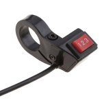
The switch. Does your switch look something like this?

EF3CFA18-ECD9-4B48-95DF-B1378D42FA38.jpeg

It sounds like it could be the switch, if you have something like this.
 
Back
Top