The exact meaning of Kv

Tiberius

10 kW
Joined
Jan 14, 2008
Messages
871
Location
Rural England
OK, some of you may already know the answer to these questions, in which case this post will tell you more about me than about motors.

Kv is the rpm per Volt. I'm talking about Permanent Magnet Brushless DC motors, but the principle applies to other types. Ie, Kv tells you how fast the motor can run at no load from a given voltage. Or its the back emf at a given rpm. Basically, it tells you the relationship between the rpm and voltage on the terminals, when there is no current flowing.

But this is a 3 phase system, with approximately sinusoidal waveforms. I've always wondered if Kv is defined in terms of the peak voltage, the rms voltage, or the peak to peak voltage. And whether it's measured from phase wire to phase wire or phase wire to the neutral position (similar to the familiar delta-wye argument). Or is it some bizarre definition based on the 6 step waveform?

Anyone else would look it up, or find a good forum to ask on. Being me, I tried to measure it. In theory, its simple enough to spin the motor up to a given rpm and measure the voltage. I did it by mounting a motor in a lathe and connecting it to a scope.LatheandMotorPorn539.jpg
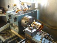
I had to make a little filter circuit to remove all the interference from the 3 phase variable frequency drive I fitted to the lathe, but other than that it all worked fine. I'm testing a Turnigy C63-64, which has 12 stators and 14 magnets. For this type of motor,the number of stators has to be a multiple of 3 and the number of magnets a multiple of 2. Its usual to make the magnets number the next convenient one up from the stators. 14 magnets is 7 pole pairs, so the frequency generated should be 7 times the rate the shaft is turning.

I tested 3 motors at the same speed and got the same results from each.

Update: I went back and rechecked the rpm measurement. I set the scope to trigger off the line waveform (50 Hz in my country) and adjusted the lathe to get 50 Hz from the motor. With a 7 pole pair motor, this means a shaft speed of 429 rpm. The lathe settings worked out as 409 rpm, so that's close enough.

Nick
 
I understand it as RMS voltage. You use the absolute values, and not a peak to peak value.

Not exactly sure how KV is pulled from one leg of a three phase motor, I knew it at one time but forgot the routine.
 
Good reading here, post 11 http://www.rcgroups.com/forums/showthread.php?t=687401

He is stating that average voltage is more important than RMS.
 
John, Miles,

Thanks for the links. Sorry, I got interrupted in the middle of the account, and I also went back and did a better calibration of the rpm. Anyway, here's what I found...

With the motor running at 429 rpm (see post above for the reason for this rpm), the quoted Kv value suggests we should see 1.86 V.

Phase wire to Phase wire measures as 4.08 Vp-p
Phase wire to Neutral measures as 2.46 Vp-p

The ratio between these values is 4% off from the theoretical square root of three, but the measurements on the scope are not wonderfully accurate, and the theory is only valid with true sine waves.

Here's the traces, and you can see that they are not perfect sine waves.

First, the phase-phase waveform
View attachment Ph-Ph Waveform_514rpm.jpg

The phase-neutral waveform
View attachment Ph-Neutral Waveform_514rpm.jpg

And for completeness, two phase to neutral waveforms (true completeness would require a 3 channel scope)
View attachment 2xPh-Neutral Waveform_514rpm.jpg

I don't see any reason why they should be perfect sines; the shape comes from the way the magnetic flux crosses the air gaps between the stators and rotors and its only certain geometries that would result in sine waves.

It turns out that there are two interpretations that come out close to the expected value. One is half the peak voltage between two phase wires. The other is the rms value of the phase to neutral waveform. Because they are not perfect sine waves I have had to estimate the rms value, and the meaning of the peak value is uncertain. In any case, the difference is minor and the measurements are not accurate enough to say which one is the true measurement.

What is clear, though, unless I've misunderstood something, is that it is not related to the voltage of the 6 step waveform that most controllers use. If you take the published Kv and use it to calculate the max rpm from the battery voltage, it will be almost a factor of 2 out. You would get a better match by taking half the battery voltage.

Nick
 
johnrobholmes said:
Good reading here, post 11 http://www.rcgroups.com/forums/showthread.php?t=687401

He is stating that average voltage is more important than RMS.

John, I think that makes sense. Rms values were originally devised for things like heating effect and charging customers according to power used. For a motor Kv, we are looking for the condition of no current flow. Where that's not possible, because the waveforms of the controller and motor BEMF are not the same, then looking for the current averaging to zero would do instead.

Nick
 
Tiberius said:
... If you take the published Kv and use it to calculate the max rpm from the battery voltage, it will be almost a factor of 2 out. You would get a better match by taking half the battery voltage.
Nick

Is this accurate? If so, it would seem to open up a lot more of the R/C motors to single stage gear reductions, and those we do see would be geared too low. For me it would be critical to have an accurate actual expected Kv for a friction drive setup in order to make an intelligent motor selection, since my roller size is fixed.

The way I've been looking at it is to take the stated Kv, multiply by the pack voltage, and then by 70% as an estimated max rpm under load. This seems to be more in line with the actual gearing people are using successfully than dividing my result by 2.

John
 
I'm not at all sure that this is accurate. For practical purposes, what I'm interested in is a definition of Kv that can be applied to predict the no-load maximum rpm of a motor at any particular supply voltage. I know that the this will, strictly speaking, be incorrect, in that there will be a small rpm loss due to the voltage drop associated with Rm and Io, but doing it this way keeps things simple when working out the size of reduction drives etc. Also, by measuring Io and Rm I can get back to a pretty good value for "pure Kv" if I need it for any purpose (like efficiency predictions).

So, here are my findings:

The first TowerPro 5330 motor I bought had a nominal Kv of 215. I changed the wiring from delta to wye and expected to get a measured Kv (using the measured no-load speed against DC supply voltage) of about 124 (215 / 1.73). I actually got a measured no-load apparent Kv against DC supply of 118, which is pretty close. If I calculate back, allowing for Rm and Io induced voltage losses at max rpm, no-load, I get a real Kv of 120.

The second motor I rewound, aiming for a Kv (again relative to DC supply voltage) of 90. In practice it turned out to be 88 when I measured it.

These two experiments make me think that, at least for these motors, the quoted Kv relates to the DC supply voltage to the controller. This may not be the correct way to derive true Kv for a three phase brushless motor, but it does have the two advantages of being easy to use and being the same as the way Kv is determined for a DC motor (i.e. related to the DC voltage).

Jeremy

PS: I measured rpm the same way as Nick, except I used one of the Hall sensor leads and ran it directly to an old (but accurate) Gould frequency counter. My motors also have 14 magnets, so there are 7 Hall pulses per rpm.
 
Jeremy- If you're going to call it off the no-load RPM when fed by a given controller voltage, in my experience, you gotta do something about timing as well.
It seems to have a lessor effect on the outrunners than the inrunners for some reason (maybe just the large KV differences), but in some simple testing I did just using my little laser tach to measure speed, and tinkering with changing the controller timing advance setting, it had a 3,200KV motor go from ~3,100KV at 0deg timing advance, to 3,800KV at the most advanced timing setting. That's a pretty substantial difference in KV if you're trying to pin a KV spec down by using RC controllers to spin the motor.
 
Sorry, I was away for a bit and let this topic slide... But I've measured another motor, and I also went back and found an error in my previous calculations, doh. Sorry.

Also, I want to take back my comments about average rather than rms values. I think we should work in rms. The reason is down to conservation of energy. This means that its always the mean power that is important, rather than the mean voltage or current.

When using a motor as a generator, its the average power through a cycle that matters, so that means working in rms voltages. Also, when running a motor from a controller, the no load speed is the point where the power flow between mechanical and electric averages to zero, not where the current averages to zero. Its a more complex analysis, but it still means that rms values are more important than average and certainly more important than peak.

I was also thinking about Luke's comment on timing. If you consider what is going on between a controller and a motor, what happens when the timing changes is interesting. The motor still runs, and it is still 100% efficient in theory. (There are no extra loss mechanisms, so if the copper is zero resistance and the iron has no eddy currents, its 100% efficient.) What does happen is that the Kv changes, and it may get less smooth in its running.

You can move the timing a long way off, and it still behaves like a good motor, albeit with a different Kv. I think this explains why people have been able to switch between Delta and Wye without seeing major timing problems, and also why they may not always see the theoretical 1.732 ratio between Delta and Wye.

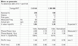
Anyway, back to the Kv measurements. Here's a spreadsheet summarising the results from two types of HXT motors.Kvspread1.gif

The 1.86 and 3.30 values are the voltages that should be seen at that rpm according to the published Kv.
Below that are the measured values, and the normalised columns are the measured values divided by the expected. I was expecting one of those normalised values to come out very close to 1.

If we consider this as a 3 phase power system, then to my mind, the only sensible number to work with is the rms Phase-Neutral voltage. But this comes out as around 0.45, out by a factor of more than 2.

Another number that could possibly be defended is sqrt(3) times that. This is on the basis that there are 3 lines carrying power, so its equivalent to one line with sqrt(3) times the voltage. It also works out as pretty much the same as the Phase-Phase rms voltage, which is more easily measured. This value comes out as around 0.77. Closer but still not very close.

One thing that would come out closer to 1 is to take half the peak to peak voltage from Phase to Phase, but that's a pretty weird measurement.

So, is there some strange convention about the definition of Kv that I'm not aware of, or are these motors labelled wrongly? The fact that 4 motors of two different types (albeit from the same manufacturer) come out with the same results argues against the latter.

In a while I will post the analysis of these numbers in terms of a 6 step controller driving the motor.

Nick
 
I find this text quite useful. In chapter "Torque & Back-EMF Constants" it states:

...the per-phase torque and bEMF functions [kt(θr), ke(θr)] are identical for a given motor and thus the per-phase torque and bEMF constants (Kt, Ke) are identical. Regardless of the motor type, the perphase Ke is defined as the peak value of line-neutral bEMF per unit angular velocity and the perphase Kt is defined as the peak value of torque per unit peak current. These definitions are always true, but they are defined in terms of line-neutral quantities which are not always measurable when a neutral connection is not available; they are rarely found on motor datasheets.

...Since in practice one is only concerned with the total torque, an “overall torque constant” can be defined for each motor (sin or trap)...
KT = 3/2 Ke (sinusoidal)
KT = 2 Ke (trapezoidal)
The uppercase subscript (sorry no subscript here) indicates that the constant describes total torque, not per-phase torque.

...Since there is no such thing as “overall” bEMF, there is no corresponding constant KE. However,
since the motor neutral is not usually available, only line-line parameters can be measured and the
bEMF constant is often specified as a line measurement, Ke,LL. Due to the way in which the two
motors are typically controlled, for the sinusoidal motor the line-line voltage is √3 larger than the
line-neutral voltage but for the trapezoidal motor the line-line voltage is twice as large as the lineneutral
voltage...
KT = √3/2 Ke,LL (sinusoidal)
KT = Ke,LL (trapezoidal)

...Finally, it must be noted that there are several variants of these values used throughout the literature and this seems to be a large point of confusion. Those given here have been selected to provide technically-accurate continuity between the per-phase and three-phase discussions. Most variants in the literature can be resolved but there have been a few which the author could not decipher...
 
Thanks rolf, that's interesting and I must study it further.

I see he agrees with me on working with line-neutral values even if the neutral isn't accessible. I like the idea of using per phase values to avoid the difficulty of overall values.

When he mentions angular velocity I immediately think of radians per sec rather than revs per minute. Another correction factor or source of confusion, I suppose.

But this seems to be the telling paragraph.

rolf_w said:
...Finally, it must be noted that there are several variants of these values used throughout the literature and this seems to be a large point of confusion. Those given here have been selected to provide technically-accurate continuity between the per-phase and three-phase discussions. Most variants in the literature can be resolved but there have been a few which the author could not decipher...[/i]

Clearly I'm not alone.

Nick
 
OK, here is the analysis with a 6 step motor controller.

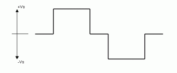
The standard controller (at WOT) applies a 3 phase, 6 step waveform to the motor. Each phase wire sees a waveform as shown below.6stepwaveform.gif
This is shown as the Phase-Neutral voltage on one phase; the other phases see similar waveforms, but spaced 120 degrees in phase.
The supply voltage to the controller is 2 Vs.

The 6 step waveform has some interesting properties in that it has no 3rd harmonic, so it is a useful substitution for a sine wave in some applications. The rms value of the waveform is sqrt(2/3).Vs or 0.816 Vs.

There is, however, a complication. During the zero volt portion of the waveform, the controller goes open circuit and lets the voltage float, rather than force it to zero. So the motor is only actually driven by the controller for 120 degrees out of every 180, for the rest its open circuit. Incidentally, this is the gap that sensorless controllers exploit to measure the back emf and work out what the motor is doing.

The way to allow for this when trying to match a 6 step controller waveform to a sine wave back emf from a motor is to work out the rms values only over the 120 degree conduction angle. For the 6 step waveform, this is the same 0.816 Vs as before. For the sine wave back emf it works out as sqrt(1/2).Vpk normally but sqrt(1/3).Vpk for the 120 degree section. Ie. the value to use is 0.577 Vpk.*

What this means is that when we overlay a controller 6 step waveform and a motor back emf sine wave so that the net power flow is zero, then the sine wave will be sqrt(2) = 1.414 the size of the 6 step waveform. During the conduction angle, they are trying to push current back and forth but the net power flow is zero. Different back emf waveforms and different controller waveforms will be different.

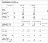
So here's the results, when I compare the HXT motors and their quoted Kv to a 6 step controller.
Kvspread2.gif

The normalised results are 0.91 and 0.87 (a perfect match would be 1.0). So its in the ballpark, but its not exact.

It is, however, the closest match seen so far. So maybe the quoted Kv really is based on the no load speed with a 6 step controller. But that does mean two things:
Anyone using a motor as a generator is going to get a surprise when he gets far more voltage than he expects.
Anyone measuring Kv using the drill or lathe method, should be applying a correction factor to get the equivalent 6 step Kv.

Nick

*I left out the interesting trig functions and integrations needed to arrive at these numbers.
 
Tiberius said:
The normalised results are 0.91 and 0.87 (a perfect match would be 1.0). So its in the ballpark, but its not exact.

It is, however, the closest match seen so far. So maybe the quoted Kv really is based on the no load speed with a 6 step controller. But that does mean two things:
Anyone using a motor as a generator is going to get a surprise when he gets far more voltage than he expects.
Anyone measuring Kv using the drill or lathe method, should be applying a correction factor to get the equivalent 6 step Kv.

Nick


Very good to know stuff!

I have to wonder why I've never spotted anyone mention this on RC groups, because they are in-love with using the drill to check KV, but then always are using block commutation of course. I guess 10% falls into the acceptable deviation area when dealing mostly with motors running 7v-22v. Great work Nick!
 
liveforphysics said:
Very good to know stuff!

I have to wonder why I've never spotted anyone mention this on RC groups, because they are in-love with using the drill to check KV, but then always are using block commutation of course. I guess 10% falls into the acceptable deviation area when dealing mostly with motors running 7v-22v. Great work Nick!

AFAIUI, block commutation at WOT is just the 6 step waveform, but I'm only using a basic model of controller operation, and I am assuming perfect timing.

I was sort of expecting someone to jump in with chapter and verse of the way this should be done, but the very fact that that hasn't happened shows its not a simple question.

As for 10% accuracy, I agree. It would be wrong to expect much better. For a start, we are not dealing with pure sine waves, though I estimate the error from that is less than 5%.

It would be useful if anyone could post waveforms and measurements from other motors.

Nick
 
A great read about power and KV measurement as related to model airplanes that I stumbled upon. Had read it years back and forgotten about it.

http://www.southernsoaringclub.org.za/a-BM-motors-5.html
 
Back
Top