inedible
100 W
I recently blew out the stock chinese controller in my scooter and have decided to replace it with this kelly KEB controller, but I'm having some trouble understanding the "precharge circuit".
Here's the diagram in the manual:
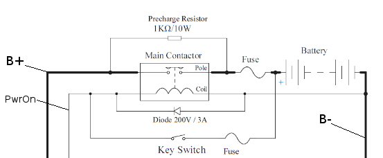
My previous controller didn't have anything like this. The key switch went straight to the PwrOn wire on the controller, without all this convoluted relay system. However, reading up on it, it seems this is necessary for like charging up the capacitors in the controller or whatnot, and without it these controllers are known to burn out.
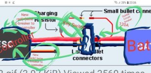
So, I've got a couple questions.. They don't mention anything about what sort of value you ought to use for this "main contactor". In fact it's never mentioned anywhere in the manual. Am I to assume I need to find a relay that can switch the full load of my bike? 66V, 60A? That seems like a lot for most relays. Do I need to find an automotive solenoid or something? Also, it looks like the coil needs to take battery voltage? All the relays I've ever seen have taken 12-24v for the coil.
Then, if I'm not mistaken, this 10W resistor is going across B+ and B- at all times, even when the bike is switched off? Isn't that A: going to waste ten watts for no goddamn reason, draining my battery? and B: going to get very hot, and I'll need to heatsink this resistor?
Following this line of reasoning, I got to wondering if I should put in a switch to switch on the precharge circuit, then, what if I put in a relay to switch on the precharge circuit when I switch on the bike, leading to an infinite loop of relays and me questioning my sanity as well as the need for a precharge circuit in the first place.
Help!
Here's the diagram in the manual:
My previous controller didn't have anything like this. The key switch went straight to the PwrOn wire on the controller, without all this convoluted relay system. However, reading up on it, it seems this is necessary for like charging up the capacitors in the controller or whatnot, and without it these controllers are known to burn out.
So, I've got a couple questions.. They don't mention anything about what sort of value you ought to use for this "main contactor". In fact it's never mentioned anywhere in the manual. Am I to assume I need to find a relay that can switch the full load of my bike? 66V, 60A? That seems like a lot for most relays. Do I need to find an automotive solenoid or something? Also, it looks like the coil needs to take battery voltage? All the relays I've ever seen have taken 12-24v for the coil.
Then, if I'm not mistaken, this 10W resistor is going across B+ and B- at all times, even when the bike is switched off? Isn't that A: going to waste ten watts for no goddamn reason, draining my battery? and B: going to get very hot, and I'll need to heatsink this resistor?
Following this line of reasoning, I got to wondering if I should put in a switch to switch on the precharge circuit, then, what if I put in a relay to switch on the precharge circuit when I switch on the bike, leading to an infinite loop of relays and me questioning my sanity as well as the need for a precharge circuit in the first place.
Help!