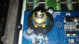
Goldenmotor VEC500. Insides + mod help

Bluefang

10 kW
Joined
Aug 27, 2010
Messages
589
Location
Australia, Goldcoast
Hey all, I have started buying a bunch of Goldenmotor items to play around with a just generally test out because i think they have the potential to do a lot better then they currently are speced for and are been used for with some simple modifications. One of the main things i have been looking at is their higher voltage controllers that go up to 120V and 40kw+ for the biggest controller. Also bought enough to get dealer pricing so thats a bonus.

I have a VEC200, VEC500 and a pair of VEC700 in my possession to test out and use as stock on a few projects. I have pulled apart the VEC500 as it was the easiest to dismantle and the simple trick i was doing with my earlier Sabvoton controllers on my motorbike does not look like it will be possible. That simple trick involved just running a parallel wire to phase wire that was going thru the hall sensor around the outside. Simple and effectively took the controllers from 10kw max to 15kw by only showing the hall sensor a portion of the phase current.

My question with the Goldenmotor controllers is does anyone have any suggestions on how to get some wire out past the massive posts? Would they be possible to unscrew, i have never seen that type so i dont know how they would have been mounted. It looks like they could be unscrewed and then i would just have to run 4x 8awg wires out, 2 from outside the hall ring and 2 from inside. The control board cannot be removed with out desoldering ~20 connections.
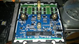
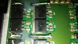
20150222_190243.jpg
20150222_190303.jpg
20150222_190410.jpg
 
Hey

Do you know how well the cooling is done?
I have the same VEC500 and it seems it overheated with constant 200A current.
It blinked led 14 times and I could drive if it cooled off.

And My plan is to install 5cm thick aluminium radiator with fins behind it 20x20cm. And then cool it with fans.
But if the cooling inside is poorly made then there is no use of my radiaor :)

Ahto
 
I asked GM about the thickness of the heat sink under the controller and i got a response that it did not have any components built into it so you could potentially cut 15-20mm slices into the heat sink opening up a ton more surface area and then just put a 120mm fan or similar in the middle to blow air through all the fins. I was planing to do similar but do it for a water cooling setup. For air cooling the slicing method using a good compound saw with a thin blade(if you are careful and happy to junk the blade going slow with a wood blade will do the job and give very thin cuts).

Do you have any power sensors on your kart like a Cycle analyst? I guess using it in a race application it would get fairly hot, are you also using regen at all with it? I personally have not gotten around to really pushing or testing out the controller properly, that is my aim to work on it this week. Really would like to know how much it can be pushed in stock form, i was getting told figures of around 20kw at 96V.
 
Hey

Yes I have Cycle analyst. And also BMS data logger.
As I have 48V battery then my limit was 250A x 48v = 12kw.
Maybe I can give it 300A max from the battery, but I do not know how to limit it, so it wouldn't take it all the time.
And I could drive 10-12 laps, eg 10-11km and then it overheated.

Ahto
 
Well your voltage is definitely the limiting factor atm. That controller will probably only handle the power you are pushing thru it because its almost always on full power been in a race kart. Using the method I suggested of slicing the heat sink and adding a fan will probably allow you to run it almost constantly at the power you currently have. If you can up the voltage then that would be the best way to more power. You should be able to get to 20kw pretty easily if you were running 72V+ and had the heat sink sliced. You don't need to know how to limit the battery as the controller will limit it for you or you could setup the Cycle analyst if its a V3 to limit battery amps to 300A.

How hot is your motor getting? Ironically if your motor can handle the extra power your controller would probably run cooler if you could push more power thru it faster allowing it more OFF time vrs the ON time it has accelerating. How does it feel driving the kart, do you have the accelerator on full all the time with only a little braking?

Derek
 
Hey

I must say that temp outside was 4 degerees of celsius :)
Motor temp was cool, If I touched it outside then it was not hotter than my body temp, so about 40 degrees celsius.
I think that my 48V motor has different inside than 72V motor, so I do not think I can input 72V.
But I was thinking of adding 12V power capacitors, about 83F and then put them in series with my 48V battery with some clever electronic board.
That way I could have a boost when needed. It seems that regen will not be enough to charge them (I had 1Ah regen when using 32Ah while driving in 12 minutes).
But there is a possibility to add 48V to 12V DC/DC 1000w converter, that will charge capacitors in 16 seconds and then I could use them like 3 second boost.

It feels good, max speed was 93km/h and lap time was 10sec slower than rotax max, lap is ~900m. It seems I need to change my gearing to less speed, because max rpm was only 3600.
It is almoust constantly accelerator to the floor :) And I have enabled automatic regen when I remove the throttle.
I have my bms logger record in every 10 sec so the graph will only show some basics, but I will order myself a CA-Logger, then I could also see the speed.
I have Cycle Analyst V2, because I read that V3 does not work with external shunt.
http://1drv.ms/1yOMs9F
 
Bah, who ever wrote that CA V3 does not work with a external shunt should be shot, revived and shot again. It requires some basic wiring to get a external shunt to work, something that building a electric vehicle i would hope anyone could do :). If you get a V3 just look at the wiring diagram for it and connect the 3 wires (blue, black, white) to the correct ends on the shunt, put the shunt value in the V3 and done. easier then figuring out what the controllers use for internal shunts :).

Your 48V motor will probably be happier at 72V, if your controller can handle 72V or more then go to the highest voltage you can with the current controller. Halve you gearing if its already too tall. DO NOT USE CAPS, they are useless for powering EVs, get some more of the same batteries you have and if you are suffering voltage sag then parallel 5ah of Nano tech lipo, you should not need to do this. Your amount of time accellerating is toooooo high, need to get more power happening so, slice the heat sink on the controller with 10-15mm cuts to be safe, increase you voltage and increase the programming on your controller. If your controller is running hotter then your motor the system is not running perfect, at max power from both the controller should be hot and the motor even hotter, slightly smokey(That point where you can smell the varnish that had not dried properly when assembled). :mrgreen:

This is a track vehicle you want it to get HOT and FAST.
 
Hey

I think the controller is universal, they just preprogram the values and sell it as separate models 48, 72, 96 in case you do not buy the programming cable.
But are you sure that 48V motor can handle 72V. In my knowledge it is 100kv motor and max rpm is 6000. So 6000rpm / 100kv = 60V.
In that case it would be only reasonable to add 12V to my 48V pack. But then I have a problem with charger as it is 48V 30A.
With 60V and 250A I would get 15kw max out of the motor.

I think that the reason motor is not hot is that the controller is VECTOR and not SQUARE. All the amps go to power and not to heat :)
Will install a big heat sink under the controller.
http://1drv.ms/1Cmq9c7
Next to the controller will make holes and 3x 7cm fans will blow air out.
The front of the sink will be closed and the back will be against a plate, soo air will go through it. In from one side and out from the fans.

With cycle analogger I will add two temp probes also. One to the motor and another to the controller. Then could see how the temps are and how motor should be geared and what should be max amps.
 
i wonder if there are some electrolytic caps between the boards. i only can see some little ceramic typs..
 
Back
Top