Ceramic Capacitor, adding some to controller DC rail

Doctorbass

100 GW
Joined
Apr 8, 2007
Messages
7,496
Location
Quebec, Canada East
I would appreciate to get some advices about those ceramic capacitors we add to the DC rail of controller to ameliorate the high current pulse response and protect fets.

I am familar with adding/or replacing caps for Low ESR caps to controller for the ripple current, but i just feel uncertain about Ceramic smaller caps.

I know they are also very important. I understand that they must help to reduce ripple current to not blow the Fets when high current demand.

Is it like adding some 104(0.1uF) or 105(1uF) or even 106(10uF) caps to the DC rail close to each phase and to the power input?

What should be their ESR or ESR per UF and voltage rating? should it be equal to the big caps ?

any exemple will be apprecaite!

Doc
 
In my approach ceramic capacitors can be used in place of the film capacitors or the snubbers. I have an example with some photos here, although this board is not fully tested yet:
http://endless-sphere.com/forums/viewtopic.php?f=30&t=65297&start=225#p1045107
They are not primarily intended to reduce the ripple current but to reduce the high voltage spike or ringing on the DC bus that happens just when the mosfets switch. I started to use ceramic caps because in my first controller I missed the film capacitors, there were no room for them, so I added ceramic ones and they worked well.
The ceramic caps are less ideal capacitors than the film caps, because their capacitance vary by temperature, but they must have lower serial inductance (ESL) because they have no legs, that is an advantage. As I saw, ESR is usually not given in the datasheet, just for some increased ESR types which are intended to use for regulators where a little ESR is needed for stability. Otherwise the ESR is said to be "very low".
To me it seems the ceramic has advantage over the film capacitor when it is placed very close to the mosfet legs, because then the inductance between the mosfet and the cap is the lowest possible. If it is placed too far then probably it has no effect at all, but it is the same for the film capacitors. Every circuit is different and if more capacitors help or not highly depend on the stray inductances, so on the circuit geometry.

Lebowski has a great analysis for these capacitors and snubbers taking into account the stray inductances, although he applied film capacitors. But one of the conclusions is that adding more capacitors is not necessarily better:
http://endless-sphere.com/forums/viewtopic.php?f=30&t=49450
 
good thread DOC.

from what i know: the higher the frequency, the bigger the advantage of ceramic caps over electrolytic. thus a logical consequence would be how much a ceramic cap helps depends on actual controller pwm or pwm duty cycle.
here i found an article: http://www.johansondielectrics.com/...-of-ceramic-chip-capacitors.html#.VVGozZOupoM
seems like NP0 is best type followed by X7R and X5R. is it right?

It really would be very interesting to see the difference in spike height if the caps are placed 1cm, 2cm or further afar away from the FETs.
 
Thanks for these info guys.

I am wondering about the voltage rating of these... For a 100V fet ( 20 or 22s used) what voltage rating the film or ceramic caps should have? is 100v enough? or better to use higher like 250V to be able to take the voltage spike ?.. or it is better to use it as snubber to protect? would they overheat

Doc
 
My intention is not to kill this interesting thread, but Fairchild clearly states this:

We should use 200V to 600V mosfets as they intented to and stop band aid things with exotic capacitors. With this sad, I'll try to use 100V mosfets that I have lying around at home on 75.6V DC rail and add some capacitors as a band-aid untill I found good 200V ones. Wish me good luck :D .
 
Doctorbass said:
I am wondering about the voltage rating of these... For a 100V fet ( 20 or 22s used) what voltage rating the film or ceramic caps should have? is 100v enough? or better to use higher like 250V to be able to take the voltage spike ?.. or it is better to use it as snubber to protect? would they overheat
I would say 100V is enough if the other components are also 100V, because if the DC bus is filtered properly the voltage should be always below 100V even with the remaining unavoidable spikes. But higher rated voltage is not a problem.
Yes the caps may overheat if the DC bus ripple voltage is too much, in this case more capacitors are needed, or lower ESR...

fellow said:
We should use 200V to 600V mosfets as they intented to and stop band aid things with exotic capacitors. With this sad, I'll try to use 100V mosfets that I have lying around at home on 75.6V DC rail and add some capacitors as a band-aid untill I found good 200V ones. Wish me good luck :D .
To me it seems Fairchild's safety margins are unnecessarily high. In battery powered systems there is no input voltage spikes, bus voltage variation (we take into account the maximum battery voltage) and other issues. I guess 20% margin should be enough in most cases, sometimes even lower.
And if you find 200V mosfets you want to remove the capacitors...? They are not just protect the mosfet but also reduce the noise that spreads everywhere on the circuit, even to the low voltage section (microcontroller, ...).
 
Removing capacitors is out of the question for the reasons you named. I just wanted to point out that better mosfets are available, and there is no need to protect them if they have high V_ds tollerance. Kind of thinking out of the box with less components. I've never had blown a single MCU or LM317 voltage regulator, those spikes always kill my mosfets first. I guess I hold the record blowing 100V IRFB4110 mosfets at 54.6V. MCU is behind the LM317 and 5V regulator, I guess those two regulators are doing resonably good job of holding those spikes in check. Last time I bought 10 quality 100v capacitors, the price was the same as the 10 mosfets of less known background.

Here are suitable to-220 package mosfets I've found so far (haven't checked their pricing yet):
1. Infineon n-channel mosfet IPP110N20N3 G V_ds=200V, RDS(on)=11mΩ
2. Infineon n-channel mosfet IPP075N15N3 G V_ds=150V, Rds_on=7.5mOhm
3. Infineon n-channel mosfet IPP041N12N3 G V_ds=120V, Rds_on=4.1mOhm
Some other packages got even lower Rds_on values.

Protecting with both capacitors and high V_ds sounds ideal, so I'm very interested in what capacitor values you guys come up with. What I don't like is to have to predict the spikes frequency before it even happens. That works on the workbech, but makes me walk long distances out in the field. By the way, Infineon states this:

The 200V and 250V product families are optimized for
applications such as Lighting for 110V AC networks, HID lamps, DC-DC converters and
Power over Ethernet (PoE).
 
Yeah, but $4.50 ea. Methods was using 6uF so $80 of capacitors.... but I don't know how many would be required for your particular application.
 
madin88 said:
guys, what do you think about this ceramic smd NP0, C0G cap:

http://www.digikey.com/product-detail/en/C2220C334J1GACTU/399-5398-2-ND/1874786

0,33µF at 100V was the largest C0G ceramic type i could find.
Looks very good, just the price is for 1000 pieces...
I use 4.7uF and 2.2uF X7R and X7S that is even worse by temperature and voltage drift, and these large caps probably have lower resonance frequency that may limit their usability, need to test.
However perhaps more of 0.33uF in parallel would be needed depending on the phase current. I guess higher current needs more capacitance because more energy is stored in the DC bus wiring inductance which needs to be absorbed by this cap.
 
HEre are some precious info that Bigmoose accepted to share with me and to the community about caps and controllers:

An article on a new hybrid cap attached from EDN "New Demands on link caps" might help.

It is good that you are separating the capacitor roles. The bulk capacitors (typically electrolytic or mylar) are to help "stiffen" the bus to counter some I^2R losses in the bus wiring during PWM. See inverter selector cap paper attached. Typically put in as many low ESR as space permits. Sized to keep temperature in check.

The snubber caps (ceramic/mylar/polypropylene)are to negate the layout impedances and are places from upper FET drain to lower FET source. They should be as close as possible to these FET leads. The best are inverter rated polypropylene if you have the space. Usually 2 to 8 uF of a good cap is enough on each leg of the H bridge.

M49470X01475KBN are excellent capacitors that I have used in many aerospace applications. It is 100V rated used on a nominal 28 Volt DC bus. These multilayer chip capacitors are known for their low equivalent series resistance and long life in power switching applications. Data sheet here: http://www.farnell.com/datasheets/1750749.pdf Trouble is they are $75 US each...

First derate any multilayer chip capacitors by 50% on voltage. For a couple of reasons. As the voltage rises, their capacitance decreases. Second, without a self fusing design, an insulation "punch through" will be catastrophic with the capacitor exploding.

As we look for "civilian rated" capacitors here are some to consider:

Vishay Sprague V-735 P High Current, Metallized Polypropylene Cap with Tabs I have used these and they are very good. They are large and have tabs, so you have to design around them. They don't retrofit well. They are very similar to commercial IGBT snubber caps used on brick IGBT's. If you can fit IGBT snubber caps they work well, are cheap second hand, but are large as they are rated at 600 and 1200 volts... way overkill for us.

Kemet F461-F464 Series as the follow on to the discontinued PHE426 are pretty good also. These are metallized film pulse capacitors with polypropylene dielectric.

I have also used GRM55DR72E105KW01L using 4 to 6 of them in parallel. In my applications I have not had a problem with them, but I believe methods mentioned that he was having some significant failures. Not sure if the problem was resolved. Whether it was a soldering problem or a dielectric problem. (I searched for the thread but can't find it... could be my memory.) The X7R loose capacitance with increased temperature. That is important for load sharing in parallel applications. Otherwise the hot cap will thermally run away.

All the best,
Dave


Doc
 
Great article! I understand that 100V on 28 DC bus is for the bulk capacitors? One person called me mad in another thread for recommending 2 times higher mosfet V_ds rating few hours ago (I do not practice what I preach, more theoretizing), here we see factor of almost 4x for the capacitors. I guess walk of shame is not an option with those devices drifting in space...

What is the appropriate voltage for snubber capacitors on H-bridges for 18s lipo (75.6V HOTC)?
 
Doctorbass said:
The snubber caps (ceramic/mylar/polypropylene)are to negate the layout impedances and are places from upper FET drain to lower FET source.
can someone explain with other words what he means with upper FET drain to lower FET source? Is it like the caps on the DC bus just as close as possible to the FET, or different?
 
Upper and lower ... AKA high side (provides power to the motor phase) and low side (return path for phase current from the motor) FETs respectively. Drain and source are legs on a MOSFET.

I know I keep harping on about methods set up, but here's one more :D
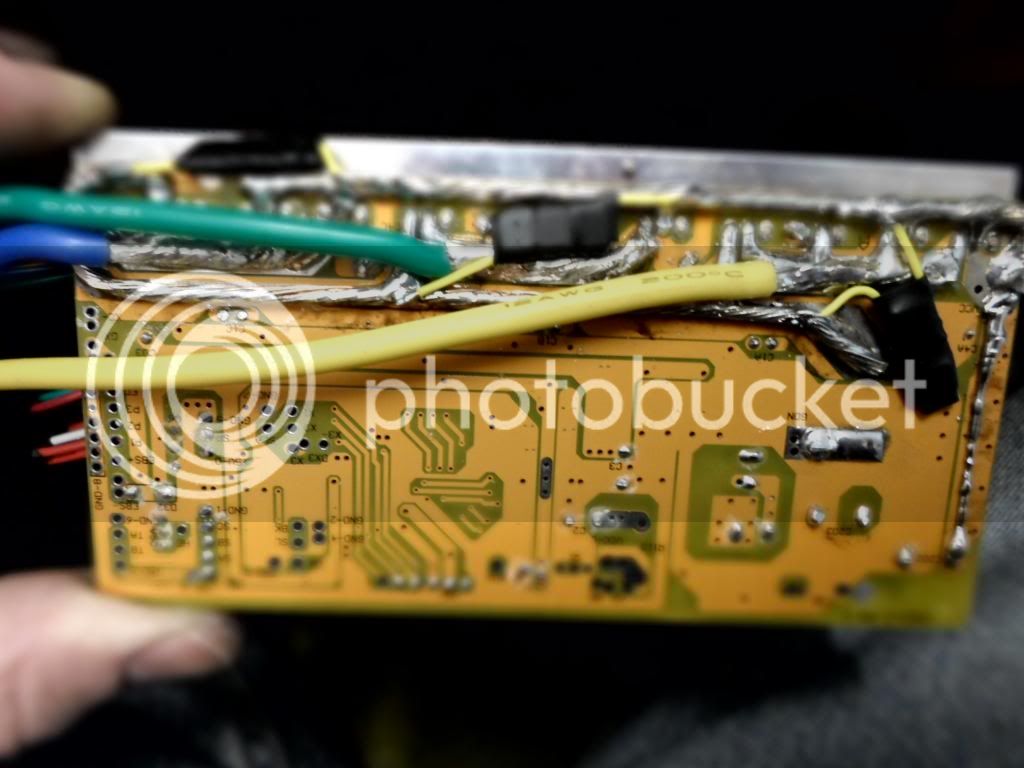
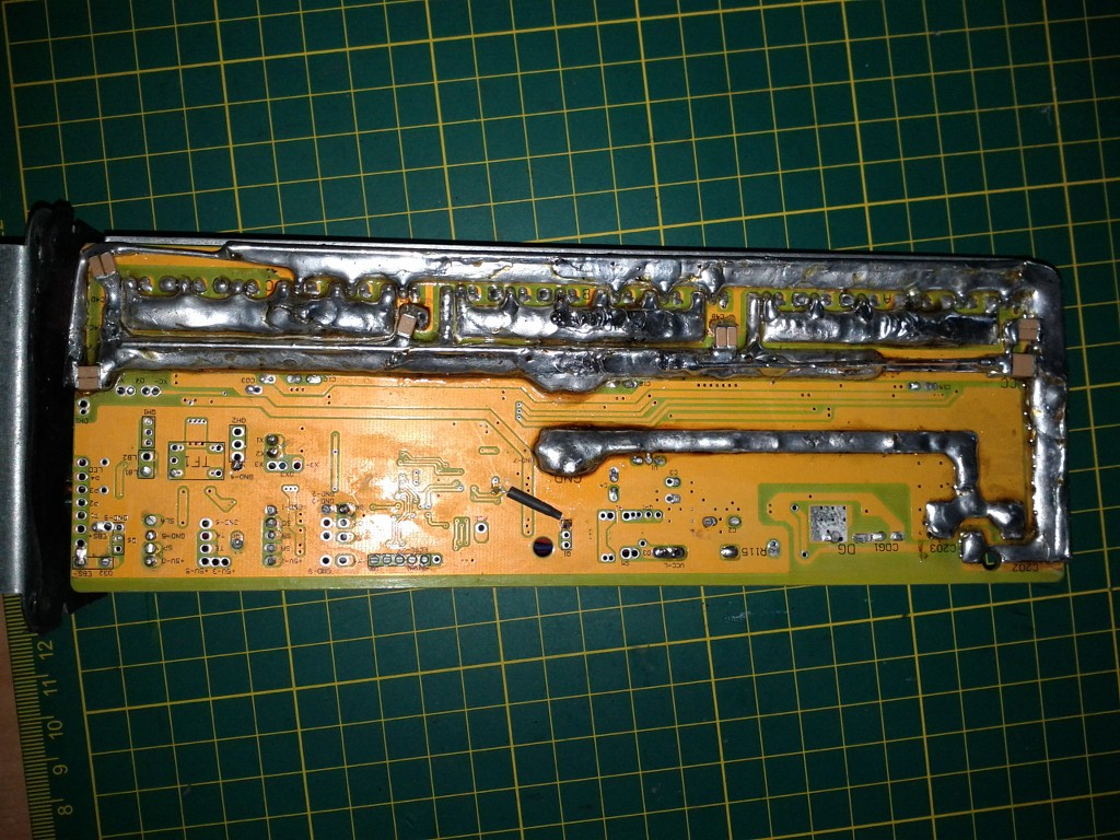
Some good pics and explanation in this thread that includes the placement on the buss and the thermal stress issues bigmoose touched on. Pics below are from this thread.

Thud
SAM_0134_zpsaa1411a8.jpg


methods
file.php
 
Gregory said:
Upper and lower ... AKA high side (provides power to the motor phase) and low side (return path for phase current from the motor) FETs respectively. Drain and source are legs on a MOSFET
i understand. thanks for your help. so they are placed exaclty like the caps on the DC rail, just with the shortest distance possible.

it looks like methods has not bothered about the thin wire going to the caps and also length. should we?
 
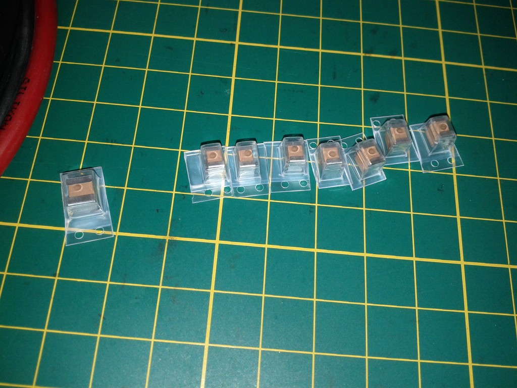
Here is a PCB with GRM55DR72E105KW01L caps installed from upper FET drain to lower FET source. Two TO247 packages are paralleled topside and bottom side. There is 6uF of GRM55DR72E105KW01L's total.

Sorry Doc I wanted to send this to you, but it took me ages to find it in my files.


Edit: Just found the methods thread where he described cracking surface mount ceramic capacitors, but it appears this was happening when he mounted them as a retrofit on the controllers he was modding. He talked of redesigns to his board, but it looks like he never made them. Thud also posted pictures of how he implemented a retrofit and said that he did not have problems similar to methods.
http://endless-sphere.com/forums/viewtopic.php?f=7&t=49379&p=729161
 
Doctorbass said:
:D Thanks!

I just placed an order for couple of these GRM55DR72E105KW01L at Digikey.

http://www.digikey.ca/scripts/DkSea...eq=172262473&uq=635672100196530087&DPU=submit

I'll put some on all my Adaptto and Lyen controllers. It will certainly help to protect at high phase amp!

Doc

this are very good caps - i believe the optimal type for modding our controllers. thanks for the nice find.
For my Adaptto upgrade i have used also 250V ceramics. in detail:
4pcs TDK 0,47µF SMD 1812 size X7R 250V on the input (about 1cm long 1mm² wires attached)
3pcs Murata o,47µF Lead Type X7R, 250V on near every FET group

NP0 / C0G types would perform better, but they have less capacitance so more would be needed and they are also much more expensive.

thats how i installed the TDK on lyen 18FET:
far right there is a pair of 2220 size 1µF TDK's
ibzw.jpg


3r1c.jpg
 
madin88 said:
Doctorbass said:
:D Thanks!

I just placed an order for couple of these GRM55DR72E105KW01L at Digikey.

http://www.digikey.ca/scripts/DkSea...eq=172262473&uq=635672100196530087&DPU=submit

I'll put some on all my Adaptto and Lyen controllers. It will certainly help to protect at high phase amp!

Doc

this are very good caps - i believe the optimal type for modding our controllers. thanks for the nice find.
For my Adaptto upgrade i have used also 250V ceramics. in detail:
4pcs TDK 0,47µF SMD 1812 size X7R 250V on the input (about 1cm long 1mm² wires attached)
3pcs Murata o,47µF Lead Type X7R, 250V on near every FET group

NP0 / C0G types would perform better, but they have less capacitance so more would be needed and they are also much more expensive.

thats how i installed the TDK on lyen 18FET:
far right there is a pair of 2220 size 1µF TDK's
ibzw.jpg


3r1c.jpg

Hi I’m newbie so excuse me for laymen advice.
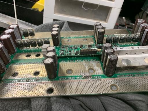
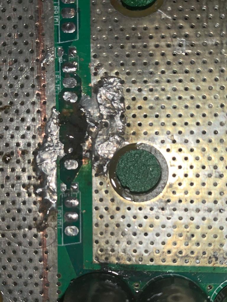
I have a kelly kac 8080i controller that I blew up 45x of60 mosfets 120n20nf upon removal of the heat dissipating aluminum I managed to break the ceramic caps next to them any one know the values these ceramic caps. I plan to fix the controller and replace the mosfets with infenion same part# 120n20nf thanks in advance also what classes can I take to learn this stuff? I’m really interested in it and it be best to know some textbook info.
13c140b6e74512414f65e77b8812e574.jpg
0d0e585566e75fbfe416b02bed191191.jpg


Sent from my iPhone using Tapatalk
 

He means he is subscribed to this thread. He wont have to look for it if someone posts new info a month from now, he will get a notice that his subscribed threads have a new post. Some people post that they have subscribed as a compliment about how good and useful the thread is.
 
spinningmagnets said:

He means he is subscribed to this thread. He wont have to look for it if someone posts new info a month from now, he will get a notice that his subscribed threads have a new post. Some people post that they have subscribed as a compliment about how good and useful the thread is.
Ahh makes perfect sense. I thought it had an answer to my question hiding in his quote... [emoji16]


Sent from my iPhone using Tapatalk
 
Back
Top