
galp
100 W
Heyo!
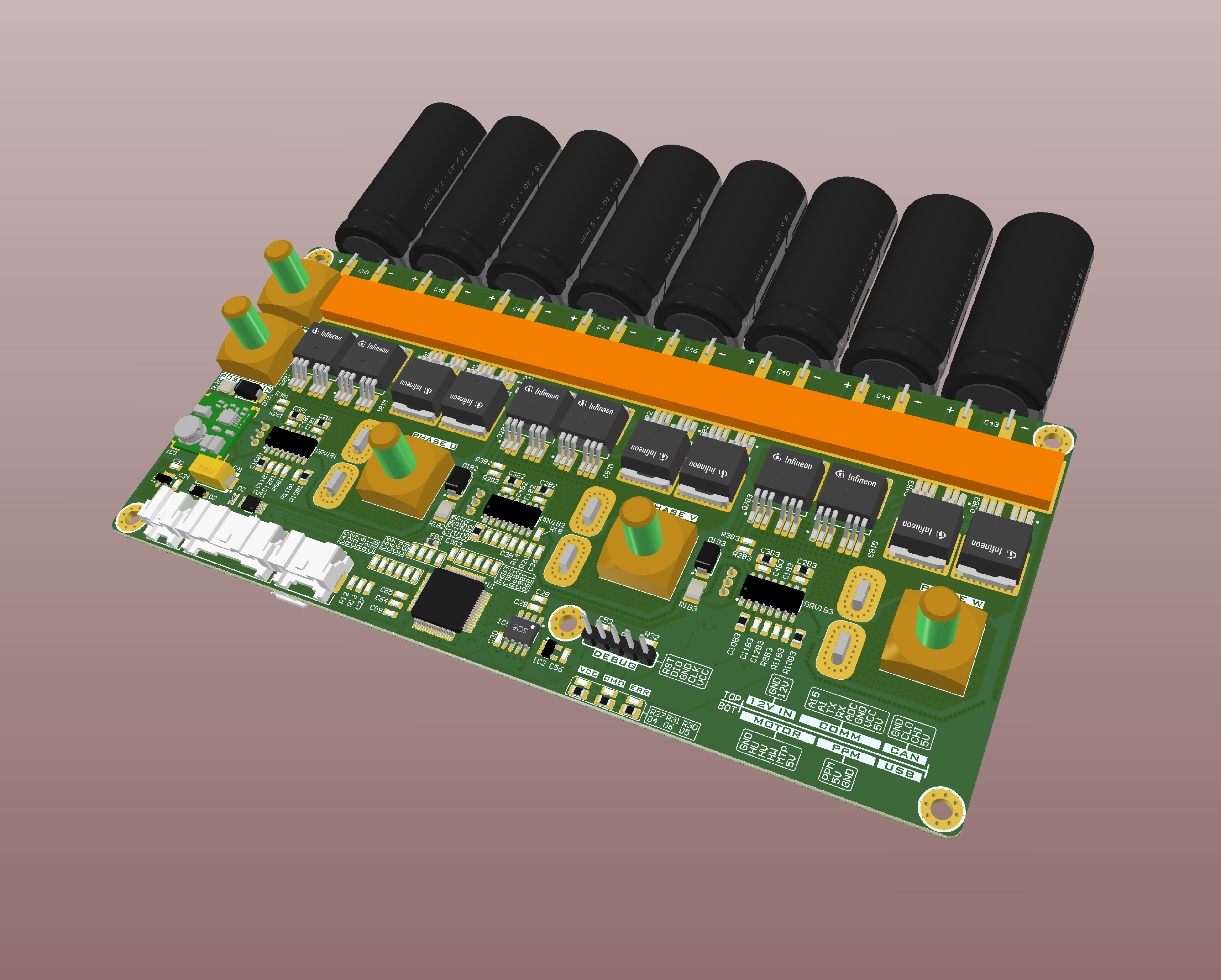
I've been working on high power VESC fork for the last couple of months. It uses VESC logic and isolated gate drivers from TI combined with high performance MOSFETs. It is designed to take maximum input voltage of 150V (30S lithium capable) and peak 200A phase/battery current.
Top side of the controller
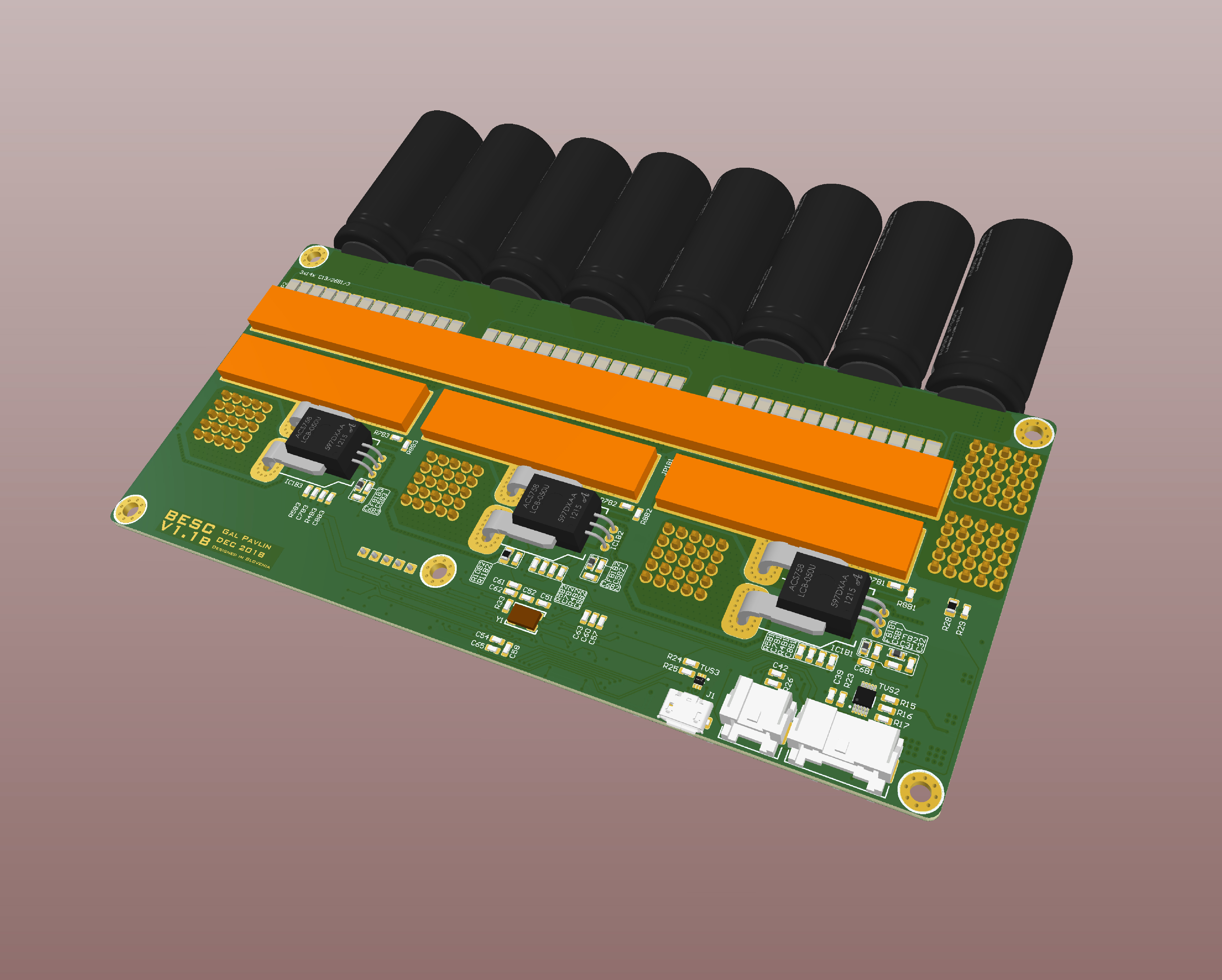
Bottom side of the controller
Features of my hardware fork:
-Input voltage: 15-150 V
-Max phase / battery current 200 A
-12 MOSFET design with high low Rdson parts
-Isolated Texas Instruments gate drivers
-Allegro 200A isolated hall current sensors
-Copper busbars for electrical and heat conduction
-Rail is decoupled with 8x 560 uF 160V aluminum and 42x 0.47 uF 200V x7r ceramics
-M6 input and output power screws[/list]
-Requires separate 12V supply - recommended Meanwell RSD-60-H
-USB, CAN, serial, I2C, SPI, 2x ADC, RC PPM inputs / outputs
-Automotive JST connectors for I/O signals
-Disconnecting 12V rail shuts down the controller - battery stays connected - no need for high current / voltage switches
Some features of VESC firmware:
-Sensored and sensorless FOC with auto-detection of all motor parameters
-Hall sensor, ABI/SPI encoder
-Current and voltage measurement on all phases
-Regenerative braking
-USB programmable and nice GUI
-Adjustable protection against
---Low input voltage
---High input voltage
---High motor current
---High input current
---High regenerative braking current (separate limits for the motor and the input)
---Rapid current changes (ramping)
---High RPM (separate limits for each direction)
---Motor and driver overheating
---... and much more
What you see on the pictures above is the second version. The first version had some problems with phase transients coupling to control signals and the whole half bridge oscillating every switch cycle. It sill ran on 50V with 70A phase currents though. I've taken care of that in second version with careful layout and stuff that I learned from the first. The last version is now complete and will be sent in fabrication soon so I can have with soldering and testing during holidays.
Here's how the first version looksed during testing:
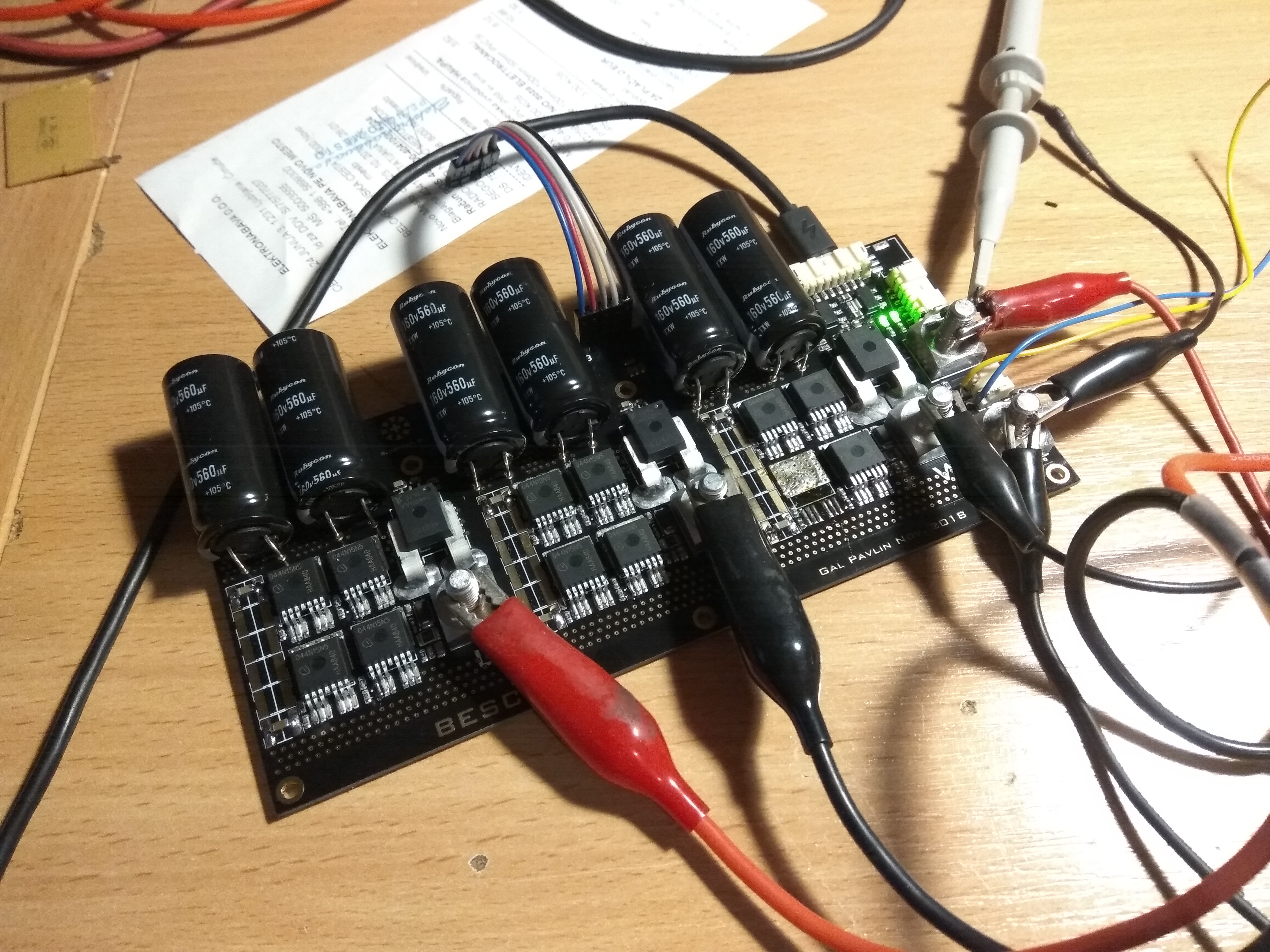
Notice one transistor missing? I fried its gate by shorting it to positive input rail with a soldering iron because I forgot to discharge the capacitors first. :|
Video of the first version running when there were still some bugs in the code configuration:
[youtube]RD5hWyjkdps[/youtube]
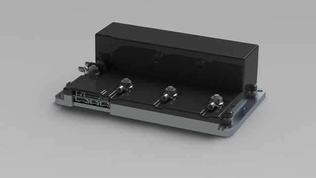
I'll CNC machine / 3d print a housing for it that will double as a heatsink.
I've been working on high power VESC fork for the last couple of months. It uses VESC logic and isolated gate drivers from TI combined with high performance MOSFETs. It is designed to take maximum input voltage of 150V (30S lithium capable) and peak 200A phase/battery current.
Top side of the controller
Bottom side of the controller
Features of my hardware fork:
-Input voltage: 15-150 V
-Max phase / battery current 200 A
-12 MOSFET design with high low Rdson parts
-Isolated Texas Instruments gate drivers
-Allegro 200A isolated hall current sensors
-Copper busbars for electrical and heat conduction
-Rail is decoupled with 8x 560 uF 160V aluminum and 42x 0.47 uF 200V x7r ceramics
-M6 input and output power screws[/list]
-Requires separate 12V supply - recommended Meanwell RSD-60-H
-USB, CAN, serial, I2C, SPI, 2x ADC, RC PPM inputs / outputs
-Automotive JST connectors for I/O signals
-Disconnecting 12V rail shuts down the controller - battery stays connected - no need for high current / voltage switches
Some features of VESC firmware:
-Sensored and sensorless FOC with auto-detection of all motor parameters
-Hall sensor, ABI/SPI encoder
-Current and voltage measurement on all phases
-Regenerative braking
-USB programmable and nice GUI
-Adjustable protection against
---Low input voltage
---High input voltage
---High motor current
---High input current
---High regenerative braking current (separate limits for the motor and the input)
---Rapid current changes (ramping)
---High RPM (separate limits for each direction)
---Motor and driver overheating
---... and much more
What you see on the pictures above is the second version. The first version had some problems with phase transients coupling to control signals and the whole half bridge oscillating every switch cycle. It sill ran on 50V with 70A phase currents though.
Here's how the first version looksed during testing:
Notice one transistor missing? I fried its gate by shorting it to positive input rail with a soldering iron because I forgot to discharge the capacitors first. :|
Video of the first version running when there were still some bugs in the code configuration:
[youtube]RD5hWyjkdps[/youtube]
I'll CNC machine / 3d print a housing for it that will double as a heatsink.


")