Lever style throttle to control a non Hall motor?

wrybread

10 mW
Joined
Feb 15, 2019
Messages
26
I've got this brushless motor:

https://www.amazon.com/gp/product/B07D9B6J78

It's controlled with a regular dial style resistive pot. I was wondering if anyone knows of a scooter style throttle that would control it?

Something like this:

https://www.amazon.com/Throttle-Control-Electric-Scooter-Pocket/dp/B01N1N29T0

Except I gather that will only work for a motor with a Hall Sensor, which mine doesn't have.
 
It doesn't matter whether your motor has hall sensors or not--what kind of throttle is used is completely irrelevant to that.


If your controller uses a potentiometer (pot) as throttle, then it is very likely that any other potentiometer based throttle would also work on it. There are a lot of them out there, but you have to be sure (check with the seller) that is the type before buying, because some put pot *and* hall in their description, or nothing, so you can't know otherwise. If they're not sure, don't buy it.
 
Well I got this throttle:

https://www.amazon.com/gp/product/B077NY8WC3/

To control this motor:

https://www.amazon.com/gp/product/B07D9B6J78/

I spliced in the 3 wires from the throttle to the motor, replacing the pot that came with the motor. It works, the throttle changes the speed of the motor, but it never comes to a complete stop.

Can anyone think of a fix for that?
 
It's a lot easier to do it the other way around: to make a pot work as a throttle on a controller expecting a hall. :(


The problems:

1: A pot based controller usually expects zero throttle to be zero volts.
2: It expects full throttle to be the full voltage it sends out to the pot (usually 5v).

1: A hall throttle never goes to zero volts; it usually goes only down to about a volt, sometimes more, which is sometimes a significant amount of throttle to the controller.
2: It also never goes up to 5v, usually less than 4v.

1: So if you used a hall sensor throttle on a potentiometer-based controller, then the hall will always output enough voltage to cause the motor to run.
2: It also will never provide full throttle, so the controller will never spin the motor at full speed/power.


This post:
https://endless-sphere.com/forums/viewtopic.php?f=2&t=5880&hilit=pot%2A+hall+throttle#p88081
gives one way you might fix the first problem, and keep the motor from running when it shouldn't.

But it will probably make the second problem even worse, by reducing the top voltage even more.


You can build an op-amp circuit (probably even just a transistor one) to compensate for this, though I don't have a diagram handy. If you don't have electronics experience, there's a lot of info over on http://allaboutcircuits.com but it may be a steep learning curve before you get to where you can figure what circuit to actually build. I can't remember exaqctly what to do at the moment, as far as which components to use and what values, but basically you just need to scale the voltage output of the hall in a way that makes it's lowest voltage zero, and it's highest voltage the full input voltage to the throttle from the controller.

I think a regular non-inverting amplifying op-amp circuit should work, but it might also require first an offset-creating op-amp circuit; I'm not sure...too tired to think about it clearly.

you could also get a couple of digipots from maxim and wire them up to each other with some other bits to convert the hall votlge to a resistance. might stil have to scale things though.

might be more info here
https://endless-sphere.com/forums/viewtopic.php?f=2&t=28466&hilit=pot+hall+throttle
or here
https://endless-sphere.com/forums/viewtopic.php?f=30&t=90837&hilit=pot*+hall*+throttle*
or in one of these
https://endless-sphere.com/forums/search.php?keywords=pot*+hall*+throttle*&terms=all&author=&sc=1&sf=firstpost&sr=topics&sk=t&sd=d&st=0&ch=300&t=0&submit=Search
 
Aha. I don't imagine you know of an inexpensive resistive handlebar style throttle?
 
The above is very helpful.

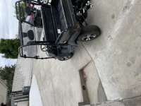
I have a question about a throttle for my 60v massimo
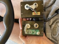
Utv. The old throttle to the left is what type? Hall or pot? The old on on the left has so many more conductors vs the replacement I found on the right. I have the issue that is has very little low end power when depressing the pedal but at full throttle it works great. ( full throttle 4.8v)
 

Attachments

  • 874166D6-527A-437E-92E6-3A2ACF0C4221.jpeg
    874166D6-527A-437E-92E6-3A2ACF0C4221.jpeg
    3.5 MB · Views: 554
Minifreakmartin said:
The old throttle to the left is what type? Hall or pot?
The picture shows them above/below each other, rather than left/right of each other, so I'm not sure which one you mean by "left" or "right" in each case.

But the one without the green circuit board appears to be a hall type, assuming that is the entire functional parts of it we can see in the picture, and there is a magnet on the end of the rotatable "wedge" shape.

The one with the green circuit board does not have enough of it's mechanics and/or electronics visible to tell what it is, since we cannot see the active moving part(s). If it is a pot throttle, there will be a potentiometer of some type being turned or moved physically in some way by the rotating / etc mechanical input. If there is no such mechanical movement, then you can look for a magnet on the moving input portion that passes by something with wires or leads coming out of it, similar to what is in the other unit (though it may look different).
 

Attachments

  • 874166D6-527A-437E-92E6-3A2ACF0C4221[1].jpeg
    874166D6-527A-437E-92E6-3A2ACF0C4221[1].jpeg
    3.5 MB · Views: 533
Thanks so much for the response. The one with the circuit board is defective and missing parts.

If its a potentiometer throttle what are all the other electronics needed on the circuit board?

Most other throttles just have a simple potentiometer and nothing else


I currently have the hall type one mounted but the utv has no low end power. Acceleration is very slow until it rolls on a hill side.

The batteries are brand new!
 
I also observed the following:


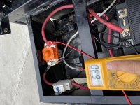
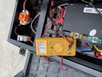
When voltage measured at solenoid it shows a 1-2v drop uphill but when measured on controller a massive drop to 30v-37v. I already changed the cable but to no avail.


Voltage drop going uphill at battery direct is from 65v to 63.4v

When level and in stands voltage drop at full throttle -bout 3v to 62v

5x 12v 100ah and 60v motor
 

Attachments

  • 3A26004C-99FA-4660-A329-C58148466FC6.jpeg
    3A26004C-99FA-4660-A329-C58148466FC6.jpeg
    3.9 MB · Views: 466
  • 6D309C25-8668-457A-B61D-5434E1AB724F.jpeg
    6D309C25-8668-457A-B61D-5434E1AB724F.jpeg
    2.9 MB · Views: 466
  • 9DA29AA4-EA2E-4DCB-BE31-02B237B878EF.jpeg
    9DA29AA4-EA2E-4DCB-BE31-02B237B878EF.jpeg
    3 MB · Views: 460
Minifreakmartin said:
The one with the circuit board is defective and missing parts.

If its a potentiometer throttle what are all the other electronics needed on the circuit board?

If it's missing parts and not working, then there's really no way to know what it is supposed to be, unless it has a manufacturer label on it somewhere to reference, and that company is still around to ask about it or left docs on line somewhere.

I zoomed way in on the image of the green PCB, and there is a part on there that looks like a hall sensor with a broken / missing leg. If so, it means the rotating piece with the magnet on it is one of the missing parts. I suppose the PCB could be electronics for "expanding" the output range of the hall sensor to match that of a pot, since a hall sensor is around 1v-4v ish, and a pot would be 0v-5v, assuming a 5v supply.

Most other throttles just have a simple potentiometer and nothing else
That's what I would expect for a pot throttle.


I currently have the hall type one mounted but the utv has no low end power. Acceleration is very slow until it rolls on a hill side.

The batteries are brand new!
The throttle type shouldn't make a difference to how much power the system has at the low end.

The possible exception is if the pot used normally is a logarithmic type, wired such that it rapidly responds at the low end and responds less and less approaching the high end. (usually you'd use a log pot the other way, so it gets gradual response at the low end, and be able to slam it on at the high end). Most of the time a linear pot would be used, and the hall response normally mimics that (though the magnet / mechanics could be designed so a hall would have log (or any other) response pattern as well).


It would make a difference in another way, however: a controller that expects a pot throttle only would typically begin responding to the throttle at a very low voltage, as little as a tenth of a volt depending on it's noise susceptibility (don't want false startups). Since a hall always outputs at least 0.7-1v, never dropping to zero, it would always be commanding the controller to spin the motor, never allowing it to stop. Fixing that would require electronics to "expand" the voltage range of the hall's output to match the expected range.

A controller designed to work with a hall throttle would not do this, as it won't respond until about 1v or so, some not until 1.4-1.5v. This means a pot, which will be starting from zero, will have a dead zone mechanically, so it doesn't start outputting anything for some significant degree of rotation. There are fixes for that, when it is a problem.
 
Minifreakmartin said:
When voltage measured at solenoid it shows a 1-2v drop uphill but when measured on controller a massive drop to 30v-37v. I already changed the cable but to no avail.
So that extreme drop is measurable across the cable, from battery to controller? Meaning, if you put your meter black lead on the controller positive input, and the meter red lead on the battery positive output, what is the voltage you read, both with no load, and under load riding?

Same for the controller negative input to the battery negative output?

This measures the actual drop across the wires and connectors, which tells you if there is a problem with resistance in them, which typically is the cause of problems like this.

If you have a contactor (solenoid) in the circuit, you can repeat the measurement on each side of it, too, to find out which side has the problem.

If you find the problem is on all wires, you may either have poor connections or insufficiently-sized wiring for the current draw.


Voltage drop going uphill at battery direct is from 65v to 63.4v
That's not too bad; how much current is being drawn at that moment?

When level and in stands voltage drop at full throttle -bout 3v to 62v
That's very wierd--you should have significantly less voltage drop on a test stand (no load) than going up a hill.
 
Back
Top