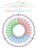
51 Slot / 50 Poles

atryz

1 mW
Joined
Apr 8, 2019
Messages
10
Hi guys,

I am working on a high resolution angular positioning system for which I cannot use any reduction.
My main requirements are:
nominal speed: 1 revolution per day
max speed: 2 RPM
control: probably ODrive through incremental optical encoder
voltage: 48V
low cogging torque
OD: 200 mm
thickness, trying to stay under 30mm
shaft: OD 80mm or so


my previous attempt was a 21 slot, 16 poles, inrunner, 35mm thick, controlled by speed control; did a few torque measurements and based on the results it would have probably worked alright.

I getting back to this after 2 years and I want to change and improve a few things.

The first thing I am switching is going to an outrunner which should yield better torque and is a better fit with the rest of the machine.
The second is an easy one: position (rotary) encoder for control.
Increasing the number of poles with a similar (even) number of poles to maximize cogging steps (i.e. reduce cogging torque).


the 51/50 combination (like most N/N-1 or N/N+1) (for big enough N slot numbers) give that weird aAaA...BbBb... cCcC windings which isn't respective the typical 120 degrees found on 12/14 (or 36/42, etc.). I am thinking due the extremely low speed requirements that this combination shouldn't be problem, but what do you guys think?

Also since the speed is super slow, is it fair to assume that 1mm lamination shouldn't be a problem? My first try used 0.5mm laminations.

any pointer would help!

cheers
 
That's an unusual application for sure. Since the speed is so low, the lamination thickness won't matter at all. I'm not sure about your commutation question. I've never run that high of a pole count before.

Another option would be to use a brushed motor with an encoder. At that speed, the brushes would last forever and the control is much simpler.
 
Thanks. Control isn't much of a problem or at least shouldn't be since I have yet to hookup the ODrive.
I was wondering if anyone had any experience with similar slot/pole combinations.
 
What size / type?

(I have an old Celestron (?) autopointer mount I need to make new gears and mounting plastics for, someday. Small scope; fun but can't see much with it in the city).
 
This is for an upgrade of a large german equatorial mount I designed in 2012 which used 12" 360-tooth worm/gear. I am not entirely sure of the capacity but it carried a 17" CDK without breaking any sweat.

The mount is no longer in service since I moved and I am thinking of upgrading to direct drive. The motors I am looking at making here will be tested on the bench before I actually look into the direct drive conversion
 
With a direct drive motor, the motor will always want to align with one of the poles and cause cogging. With an accurate position feedback and motor driver you could always be powering the motor to keep it away from the cogging points but seems like sort of a hard way to do things. It will tend to have oscillations. Is there some advantage over a geared setup or stepper motors?
 
your point on cogging is one of the driving reason for 51 slot 50 poles which yields over 2500 cogging step (low cogging torque).
but even without that the motor is position controlled.

gimbal motors in camera stabilization have the same type of controller.
 
Yes, the cogging will be close to zero with 51/50 setup. You could use a coreless or slotless design and have no cogging with a more standard pole count.

I was trying to think how you would do the windings with 51/50. Someplace I remember seeing a research paper the showed the math for all kinds of winding configurations. Since 51 is only divisible by 3 and 17 it sort of limits your possibilities. One way would be to make 3 distributed pole windings. A picture would be good here.

Since you don't need a lot of power and efficiency is not really a factor, another possible approach would be to only wind coils on some of the stator poles, as few as 3.

Once the thing gets moving, the torque needed to keep it going should be fairly steady but there will always be variations in the bearing friction, wind, etc. that would require a good feedback loop with the position sensor.

I'll have to think about it more and look for that paper.
 
Take a look at this attachment for how the slots are wound.
This unusual arrangement seems to be typical of motors with a very close number of poles and slots.
I read a paper on this a while back, it was purely theoretical and seemed like a good fit for my application, that's why I want to give this a shot.
 

Attachments

  • Y51N50P.png
    Y51N50P.png
    68.7 KB · Views: 946
Yes, that's exactly what I was thinking. It would sort of suck as a high powered bike motor, but for your application it should work.
One trick will be to position the hall sensors. A way to do this is apply a limited DC current to any pair of phase wires and allow the rotor to line up. Once the rotor is "locked in" by the stator, find a spot for the hall sensor that is right on the edge of triggering. Repeat for the other combinations of phase wires.

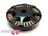
I took a look at commercial gimbal motors.
Gimbal motor2.jpg

These have a lot of poles but in a more typical configuration.
 
yeah typical gimbal motors are just a multiple of the 12/14 configuration. most of them are typically controlled by back EMF with decent results, although there are new controllers with support for quadrature encoders.

in my case, I don't use a single hall sensor but an optical encoder on each axis. I actually used RGH20 from renishaw on my original (worm/gear) design mounted on the actual RA shaft in addition to the servo motor (with encoder mounted on the motor shaft). High resolution optical encoders are required for tracking speed so low (15 arcsec/sec).
 
that's what most incremental optical encoders do (mine included) whether it's a transmissive or reflective design. The photodiodes will output sine waves. the quadrature output is generated by an interpolator. generally on the read head itself. I suspect there might be some motor controllers that can directly accept the sine as input but in my experience it makes sense to get a TTL signal just because of the substantial resolution improvement thanks to interpolation.

absolute encoders are I believe purely digital and may not rely on interpolation, but I'm not sure. Renishaw has 26bit absolute encoders and if no interpolation takes place we are probably looking at a codewheel pattern that has a pitch of about 1 arcsec. Not sure what diameter these rings are though.
 
At two revolutions per day, I would think you could get by with solid cores.
Curious though, as to what kind of torque you're going to need. How much weight, or work does this need to do?
 
Yes, solid cores would work except if you are using PWM at a high frequency, you want laminations.

Just curious how you do the commutation on that. These days I would guess you just program a microcontroller to read the position data and figure out which phase outputs to drive. In the old analog days, I would use a commutator chip, but that requires hall sensors or at least has to know when the rotor lines up with a switching point.
 
I will be making solid core prototypes and if needed we'll then go with laminations.
right now simulations are showing 100Nm stalling torque at 48V, and 80A through 2 of the 3 phases.
Hoping we can optimize this.

still need to figure out what the rated current will be, so right now the figure above doesn't have a whole lot of meaning.

telescopes are always extremely well balanced (for accuracy reasons) which means the current draw during normal operation is extremely low. The torque requirement (and more than likely pretty high current) are needed for very short period of time during acceleration (going from 0 to 10 degrees per second or so in 1 second - which is entirely debatable as being a requirement since slew speed and acceleration can be compromised as they are not how we evaluate performance a telescope mount), and wind gusts (the impact can be small or big depending on the physical size of the scope and the intensity of the wind).

so the requirements are very low overall but you need to design around external forces which are extremely difficult to evaluate. Not sure if you guys knew but the telescope in Palomar was the biggest in the world for many years and only used 1/4 HP electric motor, sure it had gear/worm reduction but driving a perfectly balance mass at such low rotation speed doesn't require a lot of power. Ensuring it spins at the right speed is a different story. Getting rid of all the gear/worm simplifies a lot of things and also removes a whole train of mechanical errors and backlashes but it also comes with its fair bit of challenges:
- torque
- high resolution encoder control
- need for failsafe braking system
- etc.
 
Since it will turn free, the dampening, or braking system may be a hurdle, and add to the power requirements?

I can see where the worm gear is the system of choice. But probably only has one speed,..slow.

Just a thought, but some hub motors are fairly close to your proposed 51/50 pole count. The Crystalyte H35 series
has a 51/46 arrangement if I remember right. Perhaps somehow useful for experimenting or pre-testing your Odrive
and optical encoder system?
 
there are a few systems using direct drive, worm/gear is still predominant though. The slower speed is not a huge problem.

thanks on the tip for the crystalyte, I will look into those now!
 
Back
Top