
damnub
1 µW
- Joined
- Apr 21, 2019
- Messages
- 4
Hello!
So im trying to get my motor to work with my controller and this have been kind of a struggle. First of, the instructions are super minimal and half chinese so I have very little to work with. I connected everything that maked sense to me. But when I connect the battery it sparks. (only 1 time, untill u wait a bit and try again) for me this seems horrible like something is terribly wrong but someone told me this is the capistors charging? After it sparked it does nothing like its disconnected. No movement, no 5V into the throttle.
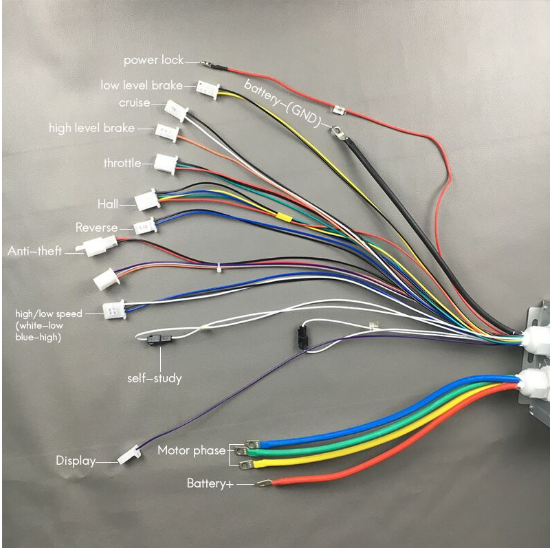
this is what im working with.
Ive gone through all the wires.
power lock - ??
low level brake - braking
cruise - ??
high level brake - also braking (?)
throttle - makes sense and its connected
hall - connected motor hall by colors
reverse - speaks for itself
anti theft - powered on makes the wheel not be able to move.
[no text] - ??
high / low speed - different power options
self study - ?? (something to do with hall sensors)
display - i dont have a display
motor phase - Connected to motor colors
battery - - connected to battery ground
battery + - connected to battery positive
Ive recorded the sparking aswell
https://www.youtube.com/watch?v=JjKPpxOqA_g&
I hope someone has experience deciphering chinese controllers")
Thanks for reading
So im trying to get my motor to work with my controller and this have been kind of a struggle. First of, the instructions are super minimal and half chinese so I have very little to work with. I connected everything that maked sense to me. But when I connect the battery it sparks. (only 1 time, untill u wait a bit and try again) for me this seems horrible like something is terribly wrong but someone told me this is the capistors charging? After it sparked it does nothing like its disconnected. No movement, no 5V into the throttle.
this is what im working with.
Ive gone through all the wires.
power lock - ??
low level brake - braking
cruise - ??
high level brake - also braking (?)
throttle - makes sense and its connected
hall - connected motor hall by colors
reverse - speaks for itself
anti theft - powered on makes the wheel not be able to move.
[no text] - ??
high / low speed - different power options
self study - ?? (something to do with hall sensors)
display - i dont have a display
motor phase - Connected to motor colors
battery - - connected to battery ground
battery + - connected to battery positive
Ive recorded the sparking aswell
https://www.youtube.com/watch?v=JjKPpxOqA_g&
I hope someone has experience deciphering chinese controllers
Thanks for reading