Need help! Electric Kart with 120100 Outrunner and Kelly Controller

opc

1 µW
Joined
Jan 12, 2020
Messages
4
Hi Fellow EV Enthusiasts!

I need help with a motor controller issue I had late last season, and that I'm just now getting around to wanting to fix. First though, I should probably provide some background.

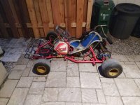
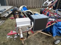
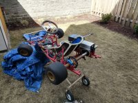
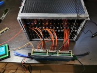
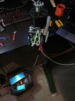
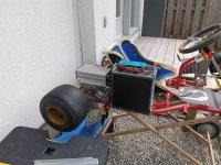
I've been swapping an existing Birel BY-30 race kart chassis from the stock 208cc ICE to a 25kW 120100 outrunner motor controlled by a Kelly KBL96351E and powered by a 32S LiFePo pack using A123 Systems AMP20M1HD-A cells.

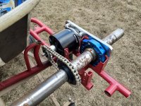
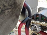
I had some adapter plates and and custom sprockets CNC machined to mount the motor, and allow for a 2:1 gear reduction via a 15T sprocket on the motor output shaft, and a 30T sprocket on the rear axle. Everything mounted up really nicely with a 420 chain, and spins smoothly with great alignment.

It took me the better part of a year to get it all up and running, and on the test stand everything seemed pretty good with the exception of the motor not running very smoothly. It made a bit of an unpleasant "tinging" sound when running in one direction, and was quite a bit smoother and quieter in the other direction. I played around with phase wiring and the hall sensors, but the results were always the same. Having no other real reference, I figured this was just the way the controller was, and took it out for its maiden voyage. Low speed control was a bit clunky, and acceleration was not all that brisk since I had the controller set to very soft acceleration settings for testing. I slowly got the kart up to speed (likely around 60kph) in an empty parking lot, and suddenly I herd a bang, followed by an abrupt lockup of the rear axel, and smoke. I hit the cutoff on the battery immediately, and hopped out. The smoke was coming from the three phase wires coming out of the motor, and the motor itself must have been close to 90-100c as a quick touch of the surface lightly burned me. At least one of the motor phases was shorted, and I pushed the kart back home with my tail between my legs.

My first reaction was to blame the crappy motor. After all, the battery is more than capable of delivering the needed power, the Kelly controllers have a reputation for being bomb-proof and excellent overall, and the motor was some cheap thing I bought off Alibaba that I had never seen anyone else use. I did a quick internet search hoping to confirm my suspicions, but instead I found this:

https://www.youtube.com/watch?v=cG7sEFBNiSQ

So yeah... doesn't look like it's a motor limitation. For the record, I was having a lot less fun than that guy when mine blew up ;)

This brought me to the controller. The fellow in the video above is using a KLS96501-8080I which is a sine-wave controller from Kelly capable of 70,000 ERPM. I had a quick look at my controller and it's only good for 40,000 ERPM and that's likely where I was when the motor self destructed. Clearly that was a critical oversight on my part given the motor is a 28 pole capable of 5000RPM with my battery voltage.

So now that you have the whole story, here's my question: Was the ERPM limitation of the controller likely my problem? Did the controller lose position and liquify one of the motor windings when the ERPM was exceeded? What's my best option to fix this? I have a backup motor, but I'd rather not blow it up as well.

Kelly offers upgrades for my controller to 70,000 ERPM or 100,000 ERPM so I could contact them and see if that's an option. To be honest though, I'm really not very happy with the lack of setup capability with that controller, and the clunky running of the motor in the forward direction. It really doesn't sound all that great, and there is no auto-tuning or diagnostics in the setup software that could help me.

Does anyone have a suggestion for a controller they know would work well with this motor? Keep in mind my battery is a little over 100V at full charge, and I would like to be able to supply 300A peaks to the motor, and at least 200A continuous.

I will attach some pictures of my setup below. Any help or suggestions would be welcome and appreciated. I will post updates here as I go along to hopefully a more successful second maiden voyage!

Cheers,
Owen
 

Attachments

  • IMG_20190506_203910.jpg
    IMG_20190506_203910.jpg
    368.5 KB · Views: 2,263
  • IMG_20200411_135337.jpg
    IMG_20200411_135337.jpg
    621 KB · Views: 2,263
  • IMG_20200411_135528.jpg
    IMG_20200411_135528.jpg
    703.2 KB · Views: 2,262
  • IMG_20200411_135558.jpg
    IMG_20200411_135558.jpg
    797.9 KB · Views: 2,262
  • IMG_20200510_152841.jpg
    IMG_20200510_152841.jpg
    306.1 KB · Views: 2,262
  • IMG_20200608_133839.jpg
    IMG_20200608_133839.jpg
    492.6 KB · Views: 2,262
  • IMG_20200621_120024.jpg
    IMG_20200621_120024.jpg
    190.6 KB · Views: 2,262
  • IMG_20200625_151927.jpg
    IMG_20200625_151927.jpg
    642.2 KB · Views: 2,263
Are you using hall sensors in the motor? If so, are they neutrally timed, or advanced or retarded timing? (the former works the same in either direction, the other two will be different operation in reverse vs forward, and can cause problems if the controller doesn't "know" about this to compensate for it at different RPMs, phase currents, etc). Also, are they 120 or 60 degree position? (the controller can do either, but has to be set correctly)

Note that in some motors, poor design or poor manufacturing can put the halls in the wrong places for what a motor is intended to do. See the Revolt motor threads for some examples.


ERPM being insufficient usualy causes loss of correct timing between phase signals and magnet positions (what the hall sensors detect) at some point, and that can cause excessive heating.


Hall signal interference can also cause problems, and typically the higher the phase currents are and/or the higher the motor RPM, the more likely this is to happen. Physically isolating the hall wire cable from the phase wire cable for as much of the distance between motor and controller can help with this, as can shielding the hall wire cable electrically.


Another potential issue that can cause overheating is if the gearing ratio between motor and wheel isnt' correct for the speed you're wanting, if there is sufficient load on the motor.
 
opc said:
Does anyone have a suggestion for a controller they know would work well with this motor? Keep in mind my battery is a little over 100V at full charge, and I would like to be able to supply 300A peaks to the motor, and at least 200A continuous.


Cheers,
Owen

They are more expensive and can be time-consuming to set up, but I really recommend Sevcon for a serious build, if you are looking for reliability and flexibility. BTW that battery build is beautiful!
 
Hi Amberwolf,

Thank you so much for the prompt reply and detailed explanation! I will respond below:

amberwolf said:
Are you using hall sensors in the motor? If so, are they neutrally timed, or advanced or retarded timing? (the former works the same in either direction, the other two will be different operation in reverse vs forward, and can cause problems if the controller doesn't "know" about this to compensate for it at different RPMs, phase currents, etc). Also, are they 120 or 60 degree position? (the controller can do either, but has to be set correctly)

Yes, the motor was ordered with the hall sensor option, and they are spaced at 120 degrees as there are 3 of them. I can see them through the top of the motor and they are small 3-pin through hole devices mounted on a PCB towards the very top edge of the rotor. As for timing, the fact that all phase and hall combinations produced the same poor behavior in the same direction (which happens to be my forward direction), would indicate that perhaps there is excessive "advance" in one direction and "delay" in the other. I would assume rotating the PCB a few degrees may correct for this to make it neutral? I definitely don't see any settings for this in the rather poor Kelly Controller software. The funny thing is that several years ago when I first hooked everything up, the Kelly SW I had at that time had many additional options, some tuning capability, and required far more information during setup. The SW I downloaded more recently has none of these options, and basically seems to be far more restricted. I no longer have the old SW and it's a shame I can't get it anymore.

amberwolf said:
Note that in some motors, poor design or poor manufacturing can put the halls in the wrong places for what a motor is intended to do. See the Revolt motor threads for some examples.

I will check the Revolt thread... could be applicable to my el-cheapo motors ;)

amberwolf said:
ERPM being insufficient usualy causes loss of correct timing between phase signals and magnet positions (what the hall sensors detect) at some point, and that can cause excessive heating.

I'm guessing this was the culprit. I noticed in the video I linked to that a small shroud was used along with a ducted fan to promote airflow, but that guy was absolutely thrashing that thing for several minutes where I barely crawled around for less than 2 minutes. I don't think the amount of heat I noticed in my motor was normal for the load it was under. Nonetheless, I will 3D print a similar shroud and I also have the liquid cooled stator option, so I will hook up a liquid cooling loop with a radiator on the front just to be safe. If it still overheats under these conditions I can be quite confident something else is wrong.

amberwolf said:
Hall signal interference can also cause problems, and typically the higher the phase currents are and/or the higher the motor RPM, the more likely this is to happen. Physically isolating the hall wire cable from the phase wire cable for as much of the distance between motor and controller can help with this, as can shielding the hall wire cable electrically.

Since the hall sensors exit in a bundle with the phase wires, this could also be an issue. I have some braided shielding, so I can use that to improve the shielding on the hall sensors, but I don't think there's much I can do about proximity as there is limited space. Again though, I had acceleration settings at the absolute minimum while testing, so I don't think phase currents were all that high at the time. Data logging would have gone a long way to help solving this, but the Kelly controller doesn't support that.

amberwolf said:
Another potential issue that can cause overheating is if the gearing ratio between motor and wheel isnt' correct for the speed you're wanting, if there is sufficient load on the motor.

I chose the gear ratio with the following rational: Motor KV=50, Battery voltage = 100V, max RPM = ~5000, wheel circumference = 0.865m, target top speed = ~120km/h. A 2:1 gear ratio gets me there, and given the stock ICE motor produces only about 9-10HP peak and can easily hit 85-90km/h this motor at a peak of 33HP should be capable of that top speed for short durations. Hopefully this is not the issue as the custom CNC sprockets were expensive!

Thanks again for your input!

Cheers,
Owen
 
everythingisawave said:
They are more expensive and can be time-consuming to set up, but I really recommend Sevcon for a serious build, if you are looking for reliability and flexibility. BTW that battery build is beautiful!

I will check out the Sevcon controllers for sure. I was also looking at the VESC 100/250 as I like the data logging and tuning aspects of that SW, but I don't know if that controller would be up for the level of abuse planned for this:

https://trampaboards.com/1x-vesc-100v-250a--350-tax-each-p-28115.html

Thank you for the kind words on the battery! It was a huge amount of work to design and implement, but I'm very happy with the outcome. It should never really be the limiting factor with this setup, and I managed to get a little over 2kWH in a package that only weighs just over 18kg including the BMS, breaker and display. It should also be capable of peak output in excess of 38kW which should be more than I will ever need for my kart application. Building it was one of the most nerve-racking experiences I've ever had, but now that it's all packaged up, balanced and tested, I'm really happy with the results. Perhaps I can start a new thread with details on that build.

Regards,
Owen
 
opc said:
Yes, the motor was ordered with the hall sensor option, and they are spaced at 120 degrees as there are 3 of them.
Just to note: Having three sensors doesn't make them spaced at 120 degrees (or any other particular position physically or electrically ;) ).


I can see them through the top of the motor and they are small 3-pin through hole devices mounted on a PCB towards the very top edge of the rotor. As for timing, the fact that all phase and hall combinations produced the same poor behavior in the same direction (which happens to be my forward direction), would indicate that perhaps there is excessive "advance" in one direction and "delay" in the other. I would assume rotating the PCB a few degrees may correct for this to make it neutral?
Moving the PCB may fix the advance/retard; whether it will fix the other issues...don't know--depends on what they're caused by. ;)

(old brushed motors often had slots instead of holes for the moutning screws of the brushes, specifically so that timing could be advanced, retarded, or made neutral).

I know there are ways to measure and calculate phase/hall alignment, but I don't know what they are. Fechter probably has posts about this, if you look thru his posts. Other people probably do, too. Most likely in threads where someone is troubleshooting problems related to yours.


I no longer have the old SW and it's a shame I can't get it anymore.
YOu might check on Archive.org and other archival sites; someone may have saved older versions there. Generally easier to find by looking up the actual file name, if you know it.


Again though, I had acceleration settings at the absolute minimum while testing, so I don't think phase currents were all that high at the time. Data logging would have gone a long way to help solving this, but the Kelly controller doesn't support that.
Phase currents even when "low" can still be high enough to induce currents into neighboring wires if they are close enough, and it's very common for hall wires to be run "in between" the phase wires to make the cable the smallest diameter possible to pass thru whatever entry point it has in the motor. :(


I chose the gear ratio with the following rational: Motor KV=50, Battery voltage = 100V, max RPM = ~5000, wheel circumference = 0.865m, target top speed = ~120km/h. A 2:1 gear ratio gets me there, and given the stock ICE motor produces only about 9-10HP peak and can easily hit 85-90km/h this motor at a peak of 33HP should be capable of that top speed for short durations.

I didn't try to do the math to see if the ratio is right, but basically if the ratio you used will let the wheel reach above the actual top speed needed (usually by around 20%) when unloaded, but not way above that speed, then it is probably ok.

The problems usually happen when something is geared for say, twice the top speed needed, or higher, because then there is less torque available at the low end without excessive motor currents (and heat). The higher it's geared, the worse the problem is.
 
Thank you for the clarification on the Hall sensor angle. I assumed incorrectly it was a physical arrangement, but I guess not.

A few updates which only serve to further muddy the waters ;)

- The controller works exactly the same regardless if it's set to 60 degree or 120 degree for the hall sensors
- Regardless of motor phase and hall connection, the sound always happens in the same direction. (motor CCW)
- The sound is just like a bicycle freewheel. Video posted below.
- The Kelly control software has a disabled motor pole setting which is set to 8. I don't think this is correct... it's a 28 pole motor, or 14 pole pairs. I cannot change this setting, but I remember it used to be accessible in older versions.
- I have all features disabled at this stage.. no regen, no smoothing, no ABS, nothing that could possibly be interfering.
- This is the backup motor mounted up, and it is behaving exactly like the one I cooked. Same sound, same direction.

I'll spend some time today getting the water cooling hooked up, and also the cooling fan shroud for the motor. Maybe I will limit it to half speed and give it another try with the acceleration turned up, but the max speed limited. Then perhaps I can tell if the excessive heat was a function of the controller not being fast enough (ERPM) or something else entirely.

Link to video of the motor running in forward and reverse:

https://photos.app.goo.gl/zwUjkTzGPZr4CBZCA

Stay tuned!
Owen
 
opc said:
Hi Fellow EV Enthusiasts!

I did a quick internet search hoping to confirm my suspicions, but instead I found this:

https://www.youtube.com/watch?v=cG7sEFBNiSQ

So yeah... doesn't look like it's a motor limitation. For the record, I was having a lot less fun than that guy when mine blew up ;)

Welcome Owen,

If you look from 0:54s in that video you'll see that guy mounted and SUPPORTED the motor (axle) the right way to use in a radially (!) loaded application. The motor you're using is a drone or plane motor that is built for axial loading through a prop. In the video you can see the guy has a support bearing plate on the axle (prop) side to prevent the motor from destroying itself by bending due to the pulling force from the chain when using some power.


Support bearing.jpg


So if you are going forward with the same type of (replacement) motor you'll have to make a support bearing.
Or buy a QS 138 70/90H motor&controller kit that is heavier build and more suited to this application.

Anyway, just my observation. Succes with (re)building and enjoy!
 
opc said:
Thank you for the clarification on the Hall sensor angle. I assumed incorrectly it was a physical arrangement, but I guess not.
The halls *can* be physically laid out at 120 degree angles...in a triangle around the motor, but this is rarely done. Usually they're on a small PCB that's tied down to the windings, with the halls inserted into slots in the laminations (often one in a groove cut in one tooth, and two in spaces between teeth on either side nearby). It's common for a 60 degree configuration to be the same but with the middle sensor flipped upside down.

- The controller works exactly the same regardless if it's set to 60 degree or 120 degree for the hall sensors
That's pretty strange. Does it work the same *without the sensors connected*?
You should get pretty different results with a controller set to one when the sensors are setup the other way. It sort of implies that the sensors are neither 60 nor 120, but some other configuration (I have no idea what it could be).


- Regardless of motor phase and hall connection, the sound always happens in the same direction. (motor CCW)
That does imply that the sensors are not in neutral timing.

- The sound is just like a bicycle freewheel.
It does sound like one...but I don't know what specifically that sound might mean.


- The Kelly control software has a disabled motor pole setting which is set to 8. I don't think this is correct... it's a 28 pole motor, or 14 pole pairs. I cannot change this setting, but I remember it used to be accessible in older versions.
Well, unless their "identification angle" procedure is also (correctly) automatically determining number of poles, then you'd need access to such a setting to make any FOC the controller has work properly, AFAIK. If it is operating based on the wrong number of poles, the waveform sent to the motor will probably not be correct.

I did some poking around on the web and have not yet found any archived versions of the kelly software. :( Still looking. Maybe you could try asking kelly for old versions?

- This is the backup motor mounted up, and it is behaving exactly like the one I cooked. Same sound, same direction.
If you don't have the motor hooked to the chain, does it make similar sounds? Or only with the load of the axle/etc on it?
 
Hi mate!

Great build!
I had a similar issue and... I upgraded to the Hi rpm controller, no more funny cogging but... No way to control timing or number of magnets in the setup so the motor was still running unefficient.

I got the answer from somewhere in the forum, forget sinusoidal controller, since the ultra high speed, squarewave controllers seem to work easier on those hi rpm motors.

Hope I could help!
Best regards!
 
Back
Top