Golf Cart

Jay64

100 kW
Joined
Nov 16, 2007
Messages
1,640
Location
St. Petersburg, Florida
I picked up an old golf cart for supper cheap. Was told it doesn't run, and that is the extent I know of what is wrong with it so far. There were no batteries in it, so I am hoping that they just died, and the previous owner didn't want to fork out the money for new ones. That might be a little unrealistic of a hope, but that's what I'm going on right now. :lol: It still has the motor, controller, and what looks like most of the electrical components. I figured that if the motor works, it probably would be worth what I paid for the whole thing. I think I'm going to jack the rear end up in the air and apply some power straight to the motor to just make sure that is at least working.
View attachment 3
The overall shape of the cart is pretty bad, but definately a decent place to work from. I am looking at fixing it up and trying some different stuff with it. I just started looking into the Florida NEV rules to see if I can make it streetable for running errands and such. So far I know I need a new left rear tire, but there is a shop close to me that sells used rims w used tires for $10. Figure I can't go wrong with that. I also know that I am definately going to have to replace the battery trays, as they are all rusted out. But depending on the batteries that I end up using, I would probably have to make some mods to this anyways, so that is no big deal.
View attachment 4
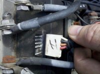
Not really sure exactly what this is, but I'm assuming that it is just to switch the motor back and forth between forward and reverse.
View attachment 1
The controller and what looks like a contactor are in pretty bad shape on the outside, but hopefully if I clean it all up, it will still work.

I believe that it is an EZ Go. Does anyone have any experience with this type of cart?
 
Jay64 said:
I think I'm going to jack the rear end up in the air and apply some power straight to the motor to just make sure that is at least working.
A series-wound motor should not be run unloaded. It will go boom.

IIRC, The BEMF drops as rpm increases, further increasing the rpm until grenading.
 
I get what you are saying, but, would it be as bad if I used a much lower voltage then the stock full voltage and ran the motor through the gearbox & axles & spun both wheels....and just did it for a moment? I'm not trying to argue with you, just trying to see how far I could push it. I planned to leave the motor installed in the cart with the wheels in the air, then just touch the lugs with a couple of leads coming off a 12v battery.
 
I was given two golf carts. I tested the motors with 24V before I began my design of a mount and pot puller for shell fish. No plasma yet. Stay with the lead. You need the amps.
 
Jay64 said:
I get what you are saying, but, would it be as bad if I used a much lower voltage then the stock full voltage and ran the motor through the gearbox & axles & spun both wheels....and just did it for a moment? I'm not trying to argue with you, just trying to see how far I could push it. I planned to leave the motor installed in the cart with the wheels in the air, then just touch the lugs with a couple of leads coming off a 12v battery.
For a functionality test, briefly could be ok, if you don't let it exceed normal max rpm.

It appears that the motor may be separately excited, so just energizing the lugs without reworking the cables may be unwise.

Stumbled on this group:
http://www.buggiesgonewild.com/electric-ezgo/3915-guide-tell-if-ezgo-series-wound-motor-seperately-excited-motor-regen-system.html
 
TD, once again, I do appreciate your input/help. Yes, I was not planning on building hardly any revs. I was thinking of having one lead connected, and then just briefly "tap" the other lead on the other lug. I just want to see if the thing will even turn when power is applied. And by using much lower than max volts, I hope that will be another check against it flying into over revs. What do you mean about reworking the cables? My plan was to disconnect all the cables from the motor and then test w power. If I remember correctly, I do have to have a pair of the lugs connected together across the motor and use the other two adding the power. It looks like all the lugs have cables going out, but I think that is because they are all hooked up to the mechanism that allows shifting into reverse. I have no idea what that thing is called, I'm just calling it the "reverser." :lol: :lol: It is in my storage unit at the moment, piled in between 8 other project chassis, so it is hard to really get into it and trace the wiring at the moment. It looks pretty crazy with a bunch of cables/wires, but thinking it through, it seems to make a lot of sense so far. If the motor works, then I will pull the whole thing out of storage and really get into it a lot closer. I have a bunch of SLAs from my 1st project. I gotta go through those and see if they are still good, and I will probably start off using those to at least get it going.
I was at an auction and saw a cart that had the body shaped into an old 50's style car. I think doing something like that would be really cool. If I get it running, I would like to make it look more like a car or truck than a cart. It has a wooden bed in the back, so I think a truck design might be good. I would like to take it with me to the races next year to help transport supplies around the track, running tires etc.
I think something like these would be pretty cool.
0803cct_02_z+nats_1950s_truck.jpg

0803cct_09_z+nats_model_a.jpg
 
This is a close up of that 3rd pic above. It seems like someone had messed with some of the wiring at some point. It seems a little ghetto for a factory job. It appears that this is the contactor that is mounted to the bracket that secures the controller in place. If I am wrong, somebody please let me know. But the wiring going to this is a little odd. (The ones with the 2nd arrow.) It appears that someone was running a wire to it, ended up about 3-4 inches short, and then just put in a short piece of wire to close the distance. BUT they didn't have thick enough wire, so they doubled it up. Or is there some reason that a factory would have done it this way?


There seems to be a bit of oxidization going on, but it looks like a lot of it could be cleaned rather easily.
 
Jay64 said:
This is a close up of that 3rd pic above. It seems like someone had messed with some of the wiring at some point. It seems a little ghetto for a factory job. It appears that this is the contactor that is mounted to the bracket that secures the controller in place. If I am wrong, somebody please let me know. But the wiring going to this is a little odd. (The ones with the 2nd arrow.) It appears that someone was running a wire to it, ended up about 3-4 inches short, and then just put in a short piece of wire to close the distance. BUT they didn't have thick enough wire, so they doubled it up. Or is there some reason that a factory would have done it this way?

I believe you are correct. That would be my guess also.
 
Most big series motors are fine running at 12V. Brush friction is enough to prevent them from overspeeding, but like TD said you don't want to use higher voltage. The series motors I'm using in my mini will run happily run at 12V all day without any load.

It's hard to tell from the photo, but that looks like a diode across the terminals you've arrowed, which suggests they're the contactor coil terminals. I'm not sure what that heavier brown wiring would be for though.

Assuming it is a series motor, which it looks like, just connect terminal A2 to S2, then connect your 12V battery to A1 and S1 to test it. The polarity doesn't matter.

That grey pick-up looks great. Wish I could get hold of one over here.
 
Thanks for all the input guys. It has been about a year since I've done any EV stuff, and I've only once worked with a series motor. So I kinda had most of the info in the back of my brain somewhere and thought I was right, but just wanted to run it by you guys to make sure. Didn't want to muck up any more components than already were mucked up.

I like the front end of that brown truck, but I kinda like the rear of the model A truck. I think I might try to do a cross between the two. Especially since I already have a wood bed anyways. For right now, I just need to get the thing running first.

Does anyone know how much voltage these things normally run on?
 
Really? That's cool. I was thinking it was about 75v or something like that. When I get it pulled out of storage I will definately get a better look at the motor and get more info from the plate if it is still there. I am trying to get as much info as I can while it is still in there, so I do appreciate your help and patience.
 
Just saw this pic posted up by Steve Clunn. This is along the lines of what I would like to do with the bodywork, with a wooden truck bed in the back.
 
Based on the spacing and size of battery trays, it is probably 48V, with four 12V FLA. Some carts use non-12V batteries, so it could be lower (24V if using 6V FLA).

The reverser is probably just a set of contactors that flip polarity on the field coil.

The controller itself may simply be a set of contactors that switches in batteries in series, as needed, for a stepped-speed control.


The motor is probably a simple series-wound motor, so if you leave the motor leads wired as they are, and simply input a single 12V FLA (car starter battery) into the two terminals from the controller itself (disconnected at the controller end), it will spin up a bit, if it works.

If it does not work, then shorting across the two motor-power terminals at the reverser should then work. If it still doesnt', then either it's a sepex motor, or it's got corrosion on the brushes/commutator, or some other problem.


If you disconnect the motor from it's physical load, be very careful that you do not spin it faster than it's nameplate RPM. It may well be able to hold together beyond that by a great amount, but if it does not, you will have a copper grenade exploding inside it as the commutator segments come off the armature at extremely high velocity. Theyv'e been known to punch thru significant thickness of comm-end vent plates, and still do damage to objects in their flight path.
 
I am in Indianapolis right now for the ice races and then heading to New Jersey for the final race of the year. Then I will be heading home to work on the cart. I don't plan to pull the motor out when I test it. I'm figuring that going through the gear box, then also spinning the wheels, and using much lower than stock volts it should be ok, just for a quick test.

Thanks for the info.
 
I had tried a few times to do a little work/testing on this while it was in my storage, but there just wasn't enough room to work on it. I just got it pulled out of my storage and was able to get to some of the parts today. First I jacked the rear end in the air so that both tires where off the ground. I pulled all the wiring off the motor and then I hooked up A1 to S2 (I had been told on a different series motor to connect the lugs diagonal to each other) and then I put a set of jumper cables to a 12 v battery, clamped on to A2 and tapped the other one against S1. At first I got a spark and nothing happened. Then I got a bit of a noise. So I held the connection on a little long and I got the wheels to spin up. So now I know that I at least have a motor that works. Next I have to figure out if the controller still works.
 
The wiring in this thing is a hot mess. There are a couple of spots where wire nuts were used to connect the wires together. I kind of want to make sure the controller works before I go through the trouble of re-wiring the whole thing. I did a very fast test with the 12v battery I had in there, just to see if by some chance it worked. It didn't. But that could be due to a LVC rather than a bad controller. But then again, it could be bad wiring too.
 
I have the motor apart gord give me right now and its pretty simple and easy to work on!
 
What motor?
 
Jay64 said:
What motor?
Its a westinghouse 4.5hp 36v golfcart motor.
 
Wow, what happened to some of my pics? Are we having problems with the pics again? I thought that had gotten resolved.

Been doing a little work with the cart again. I can't find any motor plate or any info on the controller, but the contactor does have a sticker that says 36v, so I'm going to be treating this like a 36v build, rather than the possible 48v.
36v_contactor.jpg

I put 3 12v batteries in and fixed the battery connection wiring, wired them in series and got 36.4v, they are some older SLAs that I had laying around and just threw them in for quick testing. I have some other ones on the chargers right now. This is where is starts getting a little weird. I found two switches, one is a key switch in the dash, and the other is a flip switch on the "firewall" into the motor/battery compartment, about where the passengers calves would be. (Don't know of a better way to describe that, here's a pic.)
firewall_switch.jpg

Tracing the key switch, one side goes to a connector on that reverser,
reverse_control.jpg
and the other side goes into a wiring harness that splits to both of the small lugs on the contactor, a 4 pin connection to the controller,
throttle_input.jpg
and into a box on the frame, which I'm thinking is housing the throttle pot. (Hard to get to that area at the moment, but a lever is sticking out of the box that moves with the throttle pedal, so it's my best guess.)

The "firewall" switch goes to the "red" small lug and the same side large lug on the contactor. But the weird thing is that is the not the side that the cable from the battery goes to. And, when I take a voltage read from the output lug of the contactor, I'm getting 36v no matter which switch is off or on. I don't know, there seems to be a lot of ghetto wiring on this thing, so I tend to get halfway lost trying to follow it. Maybe one of the wiring that they did isn't right. But I am getting 36v measuring from the controller B- and B+. But I'm still not getting any reaction from the motor when I press the throttle. Is there any way to test the controller output?
 

Attachments

  • throttle_input.jpg
    throttle_input.jpg
    68.6 KB · Views: 3,957
I can see it's a rat's nest, but if you can get together a crude diagram of the wiring as it stands, it will be easier to troubleshoot.
 
Ha ha. Oh man. Now that's an embarrassment. I figured it would be a good idea to try to find a general wiring diagram for a golf cart setup, so that I could use their images to modify my wiring diagram. So I googled golf cart wiring diagrams. As I was looking over the image in PS I realized that I should just use the damn wiring diagram that I was looking at. Ha ha ha.
 
Ok, now I'm making some headway. Thanks for helping me get my head out of my ass TD. Ha ha.

Model Year: 1996 Make/Model: Electric TXT Golf Car

I found this pretty cool website that pulls up the info on the cart based on the serial number. Thought I would share it just in case someone is looking for the same info later. Apparently you can also tell the year based on the last two digits of the manufacturer's number. Well, I guess the order of the numbers for that changed through the years, which makes this website even better. Now let's see if I can find an exact wiring diagram for this specific cart.
 
Back
Top