megacycle
100 kW
I was thinking about this and if and how it could work to fast charge a large Lifepo4 EV pack that has good BMS protection and where there is an ample supply available of say 150A+, 415V, 3phase.
Example 30kW pack at approx 3C in about 20 mins.
Presently only come across this type of charging for small scale wind turbines wound for 3ph and vehicle battery alternators.
View attachment 3
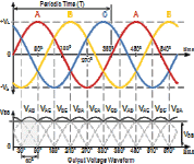
If you've seen it before, the ripple on the rectified dc waveform out, is quite a lot cleaner than a single phase supply due to six sets of interweaving rectified peaks giving this waveform.
The waveform should be further smothed by the battery acting as a very large capacitor.
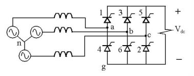
A possible improvement came to mind in using a 3 phase thyristor or IGBT bridge and a manual or controller circuit to control the voltage across the battery pack.

With resulting reduced RMS waveform
The voltage out from rectifier would be approximately 330V dc so I was thinking that a pack made up of 330/3.6 fully charged Lifepo4.
92 cells would give approx 3.58V each.
and 30kW/330V approx 90Ah each.
Any thoughts of how crazy this might be would be appreciated.
Example 30kW pack at approx 3C in about 20 mins.
Presently only come across this type of charging for small scale wind turbines wound for 3ph and vehicle battery alternators.
View attachment 3
If you've seen it before, the ripple on the rectified dc waveform out, is quite a lot cleaner than a single phase supply due to six sets of interweaving rectified peaks giving this waveform.
The waveform should be further smothed by the battery acting as a very large capacitor.

A possible improvement came to mind in using a 3 phase thyristor or IGBT bridge and a manual or controller circuit to control the voltage across the battery pack.

With resulting reduced RMS waveform
The voltage out from rectifier would be approximately 330V dc so I was thinking that a pack made up of 330/3.6 fully charged Lifepo4.
92 cells would give approx 3.58V each.
and 30kW/330V approx 90Ah each.
Any thoughts of how crazy

