Finalized! - Longboard Alien Drive Systems - single C6374

666yeti666

100 W
Joined
Jan 8, 2014
Messages
183
Dear all,
with a lot of experiences from others on this forum and another forum (http://www.elektro-skateboard.de) I will built my own electric longboard. In this thread I will show the built.

Components will be :

Deck : Vault “the doctor” 36”
Trucks : Caliber 50, 10”
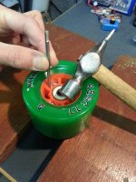
Wheels : ABEC11 83mm Flywheels 78a
Bearings : Magic Racing
Transmitter/receiver : Spektrum DX3
Batteries : Turnigy 6s 5000mAh 40-50C
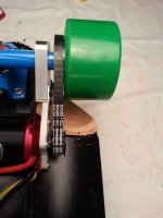
Drive train : Alien Drive systems (15/32 ratio)
Motor : C6374/08 200kV http://www.giantshark.co.uk/product/171780/c6374-08-kv200-brushless-motor (edit 13-3-2014 : this motor appeared mechanically not up to the task, the rotor shifted on the front plate. So replaced by another motor C6374 170kv from : http://alienpowersystem.com/)
Speed controller : Hobbywing Ezrun 150A

First parts are received, see below.

To be continued …

Regards
Sebastien


2014-01-15 21.25.00.jpg

2014-01-15 22.11.26.jpg
 
Does anybody have a smart, simple, light idea for an " emergency-plug" that immediately breaks the electric circuit ?

Also, does the Hobbywing Ezrun needs an anti-spark resistor, when connected to 6s lipo ? (or is it already built-in?). I would like to safe my connectors ....

thanks
Sebastien
 
666yeti666 said:
Does anybody have a smart, simple, light idea for an " emergency-plug" that immediately breaks the electric circuit ?

Also, does the Hobbywing Ezrun needs an anti-spark resistor, when connected to 6s lipo ? (or is it already built-in?). I would like to safe my connectors ....

thanks
Sebastien

It's not built in. It does not need an anti-spark resistor. Although, you can add one and it is fairly simple. I believe, they have anti-spark plugs which you can solder and make your life a bit easier. I forget the actual resistor that I bought before but I think it might be a 5 ohm or 10 ohm resistor. You simply solder the 10AWG wire or whatever wire to the end of the resistor and the other end of the resistor you solder the gold bullet connector. Basically, when you make the connection the antispark has to be connected first. You can either put it on positive or negative. Once you make the full connection and pos/neg are both plugged in while the anti-spark has already been plugged in. The resistor will absorb the spark since the current will need to travel somewhere.

Anti-spark is mostly used for more high voltage setups. You might not notice any spark with a 6S setup.

As for an emergency plug, I know beetbocks made a newer/better setup then a switch. He simply routed the pos or neg wire and looped it into a XT90 connector. On that XT90 connector it is a wire connected to itself. In a U shape what that does it complete the full power connection. On my next build I will most likely go this route. I don't have a picture or can't find one now. Maybe someone can post one for you. The switch is nice but it takes up a lot of room.
 
Can't wait to see your finished product. I found a few here for a battery holder as well for anyone with a 3D Printer - http://www.thingiverse.com/search?q=lipo+battery&sa=. I ended up printing this one http://www.thingiverse.com/thing:145966. I simply did a test print and scaled it to my specifications. It will make it easier to mount/dismount and I can always put a secondary cover on top of it.
 
daverobson08 said:
Nice work on that battery holder. Do the batteries remain exposed? Or are they held inside another enclosure?

At first I will keep the battery exposed, but I am thinking about a decent but light protection cover plate, maybe a carbon plate, to prevent damage by stonechippings.

torqueboards said:
Can't wait to see your finished product. I found a few here for a battery holder as well for anyone with a 3D Printer - http://www.thingiverse.com/search?q=lipo+battery&sa=. I ended up printing this one http://www.thingiverse.com/thing:145966. I simply did a test print and scaled it to my specifications. It will make it easier to mount/dismount and I can always put a secondary cover on top of it

It shurely looks nice nut I do not have access to any 3D printer ....


My electric system will gonna look as follows :

electr-skbrd-electronics_.jpg

regards
Sebastien
 
I want to use my longboard for driving to my work. Then I have to cross a bridge which is used by many bicyclists, of which are a lot of young students which have the ability to drive unpredictable …
Also this bridge is quite long and is very smooth, which would cause a pick up of speed significantly.
To make my point, I need a reliable braking of my board. Therefore I was thinking to place the drivetrrain on the FRONT wheel ( a car has the largest brakes at the front as well). Can anybody tell me, from experience in practice, if (electric) braking is significant more effective when the drive train is at the FRONT wheel ???

Thanks
Sebastien
 
Hi Sebastien. I run a front wheel drive with a single motor. The braking is good, but sometimes cuts out under heavy braking (I think the ESC is freaking out because of high amps). I've read that a dual motor is better for braking, and even better, a dual sensored.

I think front is better for braking, because when you brake, the weight shifts forward, so puts more pressure and more grip into the braking wheel. With the brake at the back, you could risk skidding. That's just my theory, I have no real evidence to back me up :)
 
Hello!

I have a factory made board similar to fiik 600W, it has the motor connected to one rear wheel. The eletric braking is just amazing. From 20 km/h it stops on a spot and throws you off if you not prepared and apply full brake. It has solid rubber wheels. They have electronicly controlled ABS brakes so it can't skidding.

But remember this bord has a brushed motor with a controller made for it, not a RC-controller.

Br
 
ok, thanks all. Will try to test either side of the board for the motor (reversing of the motor is easy, inly swap 2 of the 3 motorwires) .

2 diagonal drive is very nice indeed but will double the cost, so let me first try a single drive ....

The factory board will ne nice then, but of course comes with a price.
 
Received the Alien Drive System (caliber 15/32) kit today and started unpacking.
Some remarks :
- very nice CNC machined (with some small burrs here and there)
- the motor mountingplate is from another type of aluminum and not so shinY (why? I have no idea!)
- the motor mountingplate looks fragile considering it has to caay a 750gram motor. Time will tell id it's beefy enough
- the bolts are stainless steel and the one for the maingear are torx
- 5 torx bolts to hold the maingear are not all foreseen with locktite , so I did

Then I checked the motor to see if the windigs did not have a short circuit to the housing, since this could blow your ESC (don't ask me how I know...)

I also started by making the slot for the keyway in the motorshaft, by using a Dremel with a doubled sandingdisk.
Removed the ring on the shaft with a proper tool and pulled the rotor off. Then wrapped the rotor in a plastig bag and covered the axle, all to prevent metal debris covering the (very strong) motormagnets. Clamped it carefully in a vice , with wooden plates to protect it.
Made a rough drawing for the slot and started, bit by bit. After half an hour the keyway fitted properly. As you can see in the pictures below, the slot is a little to deep, but due to the not perfect 90 degrees sides, the keyway doesn't "fall in" , remains on it's place and has enough "flesh" for a good grip.

Now waiting for the ESC and the ABS cover for the other electronics.

to be continued...

regards
Sebastien


2014-01-24 13.00.00.jpg

2014-01-24 13.01.01.jpg

2014-01-24 13.01.34.jpg

2014-01-24 13.03.34.jpg

2014-01-24 13.06.06.jpg

2014-01-24 13.06.31.jpg

2014-01-24 13.10.57.jpg

2014-01-24 13.11.17.jpg

View attachment 8

2014-01-24 13.16.40.jpg

2014-01-24 13.24.41.jpg

2014-01-24 13.31.18.jpg

View attachment 4

2014-01-24 14.24.55.jpg

2014-01-24 14.32.00.jpg

2014-01-24 15.03.00.jpg

2014-01-24 15.03.25.jpg
 
Great pics bro, Thank you for being so detailed it really gives us a sense of what to expect when putting together our own boards with those pieces. I cant wait to see the finished product.
 
So I found the time to put on the ADS system to the board.

Removed one wheel and inserted the wheelhub. The first 98% can be done by hand, but the last portion must be done by tapping on the hub via a piece of wood to prevent the hub from damage of course.
Then put it back and tested its fitting by spinning the wheel by hand. Obviously it was wobbling !

http://youtu.be/7X75zWDKDkk

Then removed the wheelhub (by putting the wheel on two wooden plates and carefully tap the 3 pieces of the hub that protrude through the wheels, one by one at a time) and put it into other slot of the wheel. Finally found a position with almost no wobble.
Then I testfitted the ring with the 3 holes in it and discovered that there is a significant amount of space of 5mm between the 3 protruding pieces of the hub and the ring. When I would put in the 3 screws in, the ring would bend. So I decided to put 3 spacers in between the hub and the ring, which just fitted in. Then put the 3 stainless screws in and fixed it with blue locktite of course.
I don’t know if this is a design flaw since the wheelhub cannot protrude enough through the ABEC11 wheel, but it is solved know (I will ask Richard later on).

Then removed the wheel again in order to put the clamp on the truck. Then put the motor on the motorclamp, decided to use 4 rings between the bolts and the mount and fixed the 4 bolts (&blue locktite!).
Next thing is to put the motorclamp on the “truckclamp”, where two things must be noticed: proper alignment for straight running of the belt and belt-tension.
First the belt is hold into place on the motorpinion, then slide the wheel onto the truck axle and by rotating slowly, you can press the belt onto the wheelpulley, bit by bit. Then give the belt a little tension and fix the bolt closest to the motor. Then spin the wheel and check if the belt keeps on running on the wheelpulley. When it is skewed you will notice that the belt will want to run of the pulley. So unscrew the big bolt on the “truckclamp” and carefully tap it left or right (depening on the alignment of course) and fix it again until the belt remains well on the pulley.
Then loosen the screw on the motorclamp and carefully move (tap) to get more belt tension.
The belt may be pressed in somewhat. When giving the wheel a turn it should be running smooth. A too tight belt may cost you motorbearings. A too loose belt may skip teeth.
Finally you have to remove the wheel again in order to tighten the 4 bolts on the motorclamp (blue locktite!)

Finally this is where I ended up with the belt tension : http://youtu.be/HWy6UO3jLWA

Another thing is that you don't forget to test if you have enough space between the motor and the board when the truck is fully pressed in at either side.

Now I’m waiting for some hardware and electronics …..


20140127_190654.jpg
View attachment 14
20140127_191058.jpg
20140127_191422.jpg
View attachment 11
20140127_191915.jpg
20140127_203238.jpg
20140127_203015.jpg
20140127_203110.jpg
20140127_203446.jpg
20140127_203720.jpg
20140127_213045.jpg
View attachment 2
20140127_213732.jpg
 

Attachments

  • 20140127_213751.jpg
    20140127_213751.jpg
    60.9 KB · Views: 11,912
  • 20140127_191915.jpg
    20140127_191915.jpg
    101.7 KB · Views: 11,912
666yeti666 said:
Received the Alien Drive System (caliber 15/32) kit today and started unpacking.
S
- the motor mountingplate is from another type of aluminum and not so shinY (why? I have no idea!)

The alloy is the same 6082 grade as the rest of the kit- it is cut by a water jet then tumbled in an abrasive machine to remove sharp edges- thus it has this appearance.

- the bolts are stainless steel and the one for the maingear are torx
- 5 torx bolts to hold the maingear are not all foreseen with locktite , so I did

These bolts all have loctite applied by myself.

With regards the hub retainer- the bolts are not designed to pull; the hub into the wheel- as you pointed out a wooden block or mallet is best to knock it in with then the hub should but up against the back face of the wheel - the bolts are there to just hold it in position.The driving is done by the 3 drive legs and the hub is a very tight fit in the wheel.
I hope this helps- ..the build is looking great by the way.
 
I got some progress on the built-in of the electronics.
I thought I’ve had choosen a large enclosure (160x80x50mm) but it appeared to be small to fit everything in…

I started with where to locate all the stuff inside the box, which is made of tough ABS so quite sturdy.
The ESC had to be placed outside the middle in order to safe some room for the lcd display of the Eagletree dataloggger and to some distance from the edge otherwise the motorwires would bent too much. (I replaced these by a little thinner ones)
For proper cooling a square hole was made into the lid. The ESC will be hold into place by double sided tape (also to protect vibrations which electronics don’t like) and one small Velcro strap.
The battery- and motorwires are running through rubber grommets, to prevent damage.
Then the holes are made for the LCD display and the XT-90 “emergency-connector”. In order to fit the XT-90 , I took a small L-shaped aluminum profile and made small holes into it (better hold to the glue), then glued it with 5 minute epoxy onto the connector. Then drilled a 3mm hole into it so it can be secured to the enclosure (and removed if needed!).
In front of the LCD screen I placed a thin piece of plastic sheet to protect it from chippings. To keep it into place I’ve glued a kind of “foam frame” in which it is pressed. At the back closed it also with foam. The space between this and the ESC is also filled with some foam.

Then soldered the eagletree datalogger into place, between the ESC and the wire to the battery. Again also used a piece of foam for vibration protection.
At the bottom, on its side, in front of the ESC the receiver could be mounted on a piece of double sided tape.
There is just some small room for the ESC switch and the longer ESC wires. (I decided to skip the fuse, due to the fact that the ESC has a built-in protection, I I can reach the batteryconnectors easy as well as the emergency connector...)

I managed to mount everything inside the enclosure while preventing it from putting it close to the ‘radiating’/‘dirty’ motorwires to prevent disturbances.

I also wanted to have a mini USB connection in the box to connect the eagletree datalogger to a PC, but I doubt if it can be put in still …

The total box will be mounted on the board with 6 screws, via a layer of thin foam, to protect from vibrations. In front the battery holder will find its place. The batterywarning will be put on the edge of it.
It baterytray will stay open and after some time I will check if want to have it closed.

To be continued ….
Regards
Sebastien


20140209_210554.jpg

View attachment 4

20140209_222920.jpg

20140209_222934.jpg

20140209_222942.jpg

20140209_223125.jpg
 
Back
Top