The topic of a proper power switch comes up again and again and the options so far are quite limited (high amp car hifi breaker, connector loop, 60€ aps switch which is very out of stock). Now I asked a friend about it and he told me we could basically use a mosfet for switching. As far as I understand they can work just like a relay but are less bulky and way cheaper, if we find one that has the right specs for the job. Can anyone with more electrical knowledge chime in? I suppose there must be some reason that prevents them from being used?
You are using an out of date browser. It may not display this or other websites correctly.
You should upgrade or use an alternative browser.
You should upgrade or use an alternative browser.
Using a mosfet as a switch?
- Thread starter furp
- Start date

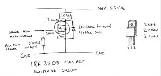
This is the circuit i use as a switch to drive higher voltage loads from a microcontroller (arduino, pic etc). It's pretty tried and tested for pumps, fans and lights we use on the electric cars at work. I'm not sure if this would be suitable as a main switch for battery connection on an e-board, but it is pretty useful.
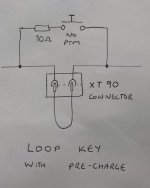
My understanding of the problem with switches and DC is the arcing when the contacts become close, but before they come into contact. This causes the switch contacts to either weld together or degrade quickly as the arcs burn material off the surface on each switch operation. The onrush current is caused by the initial charge of the capacitor on your ESC. However if the voltages on each side of the switch are the same and the capacitor is charged, there shouldn't be any voltage difference to drive current to create an arc. I've made a loop key with a precharge button that uses a 10 ohm resistor, which eliminates the arcing when you plug it in as the capacitor is charged. It works great! (on the diagram NO means normally open and PTM means Push To Make, as the button is only conducting when the button is pushed)

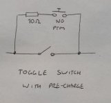
Is there any reason this same concept shouldn't be used for a normal toggle switch to eliminate arcing by providing an alternative route for the current while the switch is being switched? This would be a lot easier than using a mosfet! You'd just press the button when switching the board on and off without any arcing problems.

no, wait, i've just caught up with myself. You'd need a switch that could happily conduct 70 or so amps continuous while closed without getting hot, i'm not sure how many of those there are about. a quick search of toggle switches on RS doesn't look promising
Anyway, i'll do some testing using a toggle switch on an XT90 to replace my loop key once i've got my board finished.
Anyway, i'll do some testing using a toggle switch on an XT90 to replace my loop key once i've got my board finished.
See this summary post of designs in the thread: Active pre-charge/inrush control.
Explanations of linear charge rate in that thread explain the reason for the particular design. Charging caps is a different problem than controlling a constant load...
Calculator for number of FETs can be found in this post.
Explanations of linear charge rate in that thread explain the reason for the particular design. Charging caps is a different problem than controlling a constant load...
Calculator for number of FETs can be found in this post.
Nice to know it works in principle!
After hours of searching the only high amp mechanical switches I found were said breakers and car/boat battery switches. Both are quite bulky and not really nice to mount on a board. I have a breaker and precharge like your drawing in my MTB and a ec5 loop on my street board. Both works fine but is just not as convenient as a normal small switch.
It would be best to have the load switching done by a small circuit and operate it with any small switch, maybe a dust/water proof one or a proper key like on ebikes (would have to be possible to turn it on and pull the key back out tho), key switch with dust/water cover would be so good!
dnmun
1 PW
you can turn the battery on and off by turning the circuit current off and that turns off the output mosfets.
or you can put a switch on the gate source legs and short the gate to the source to turn them off.
or you can put a switch on the gate source legs and short the gate to the source to turn them off.
I have actually ordered 10 PCBs for doing just that, using the same MOSFET as the VESCs use. Two in parallell, so is should handle 100A continuously and 300A peak or more.
Size: 40x32mm
Current cont: 100A
Current peak: 300A
Voltage: 14V - 55V (4S to 12S)
Price: about 10€ for the PCB and components.
It can be switched on either with a tiny switch between two terminals or a 12V to 55V signal. Another feature that it has is slow turn on, which means that there will be no spark when connecting the battery even when the switch is on. It also has two pads with the right spacing for car fuses, so I plan to solder one or two parallel car fuses to them as well.
I have used a prototype of this switch on my 12S longboard for a while without problems, but I need to test the new ones once I receive them. Soldering the components to the PCB should be easy. It is very important the the PCB is protected from water since the impedance is high.
Here is a render:


mccloed
100 W
vedder said:I have actually ordered 10 PCBs for doing just that, using the same MOSFET as the VESCs use. Two in parallell, so is should handle 100A continuously and 300A peak or more.
I encourage you to review the discussion in the thread I linked above - in particular this post and this post - though there are other posts in the thread discussing design refinements and board layouts...mccloed said:I made this switch with two BTS555 mosfets, yesterday. Seems to work.
The design above is adequate for controllers with small caps/low voltages, but has otherwise been proven to eat FETs. It is very situation-dependent and sometimes works but often does not. The referenced design uses a revised RC scheme that enforces a linear charge rate to save the FETs and uses about the same number of parts. This is probably not an issue for skateboard applications, but be aware the more obvious design illustrated above has demonstrated limitations.
torqueboards
1 MW
Sweet on on/off switch Ben. I'd like a few of those too.
teklektik said:vedder said:I have actually ordered 10 PCBs for doing just that, using the same MOSFET as the VESCs use. Two in parallell, so is should handle 100A continuously and 300A peak or more.I encourage you to review the discussion in the thread I linked above - in particular this post and this post - though there are other posts in the thread discussing design refinements and board layouts...mccloed said:I made this switch with two BTS555 mosfets, yesterday. Seems to work.
The design above is adequate for controllers with small caps/low voltages, but has otherwise been proven to eat FETs. It is very situation-dependent and sometimes works but often does not. The referenced design uses a revised RC scheme that enforces a linear charge rate to save the FETs and uses about the same number of parts. This is probably not an issue for skateboard applications, but be aware the more obvious design illustrated above has demonstrated limitations.
This one seems really clever, didn't think about that:
http://endless-sphere.com/forums/viewtopic.php?f=3&t=40142&start=100#p693982
I actually made a different switch before which would kill FETs now and then because it turned on too quickly, so I added delay to the turn on time with the high value resistors and capacitors. So far it has been working fine, but I will also try the one with feedback.
mccloed
100 W
teklektik said:vedder said:I have actually ordered 10 PCBs for doing just that, using the same MOSFET as the VESCs use. Two in parallell, so is should handle 100A continuously and 300A peak or more.I encourage you to review the discussion in the thread I linked above - in particular this post and this post - though there are other posts in the thread discussing design refinements and board layouts...mccloed said:I made this switch with two BTS555 mosfets, yesterday. Seems to work.
The design above is adequate for controllers with small caps/low voltages, but has otherwise been proven to eat FETs. It is very situation-dependent and sometimes works but often does not. The referenced design uses a revised RC scheme that enforces a linear charge rate to save the FETs and uses about the same number of parts. This is probably not an issue for skateboard applications, but be aware the more obvious design illustrated above has demonstrated limitations.
Good to know. I have very limited knowledge of complex electronics so this was kind of a trial for me. Thanks for the advice.
I am wondering how the FET switch impacts voltage ripple at the ESC input. My understanding of the PWM switching for brushless drives makes the battery current take positive and negative values at the switching frequency. Using low ESR capacitors (10mOhm ?) in parallel with the Lipo (10mOhm for fresh battery ?) causes the ripple current to be shared between capacitor and battery, but still, there is some reverse current flow to the battery, so going through the FET switch.
I imagine the FET diode will allow reverse current to flow, but this would require a high voltage ripple (typically 1.2volts) so using a FET switch, I think, the capacitor has to handle a higher share of the current ripple, if not all. Did anybody notice this ?
I would tend to prefer "mechanical" solutions using a power resistor mounted inside the connector, so as to create contact first, and charge the capacitor through the resistor before the actual higly conductive parts come into contact. I use 4.7Ohm 3Watts resistor with 12s Lipo to charge my 1500uF caps.
Otherwise, it may be possible to add a sleep mode to the ESC (with total current consumption below a few 10th of microamps), so we could even leave the ESC permanently connected to the battery. I think it is feasible with the VESC, but requires some firmware changes (and possibly some hardware changes too)
Edit: Reading again my post, I notice I was wrong regarding current flowing back to the battery when motor is under load. Maybe still a risk of overheating the switches FETs during regen: for instance at 20Amps reverse current, the FETs will dissipate more than 20 Watts, and probably not for a long time.
rodgah
10 kW
This has been done before....methods i think had a design he was working on. And there is this one ..... https://endless-sphere.com/forums/viewtopic.php?f=14&t=54225.
I would take 10 if I could get my hands on them :lol:
I would take 10 if I could get my hands on them :lol:
I have thought about that as well, maybe there could be a power saving mode. Basically we would only need a switch that turns off the motors or tells the vesc to lock them and if possible a lv cutoff just in case. But I guess if that would be an option, Benjamin Vedder would have done it. Still, would be sweet to save space by adding that functionality to the vesc.
On my VESC, I measure 18.8mA idle current (on 48Volts battery) (VESC only, with just a 10kOhm potentiometer as a command).
This current seems to be higher than the long term current reported by Marcin (4.4mA average on 6s).
It might be possible to reduce the idle current using EN_GATE on DRV8302, and also by using low power mode on the STM micro. Still there will be more than 1mA (on 48Volts) due to the resistors providing battery voltage measurement to the microcontroller.
So this might be mostly software changes, but still easier to say then to implement.. especially to make sur it starts up again seamlessly
vedder said:my latest design + BOM that uses feedback from drain on the output to get a linear voltage ramp:
https://github.com/vedderb/SparkSwitch
Hi Ben,
Any news on this new design ?
Have you had the chance to test the new PCBs ? :wink:
chaka
1 kW
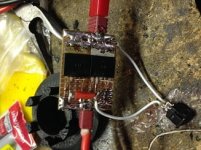
I'm running basically the same schematic with protoboard and it works well. Power up and shut down have about a 1/2 sec delay on a 33.6v system. If you cycle the switch repeatedly for a time it will heat up a bit, not enough to worry but worth noting.
sl33py
10 kW
So dumb question time - how do you get the files from Vedder's github into production? I undestand the BOM and ordering from Mouser... but how to get the PCB's for these made?
And an ultra low tech option is the anti-spark loop key. For us mere mortals who can't design or build one of these from scratch!
And an ultra low tech option is the anti-spark loop key. For us mere mortals who can't design or build one of these from scratch!
Similar threads
- Replies
- 9
- Views
- 966
- Replies
- 72
- Views
- 5,708
- Replies
- 3
- Views
- 1,552


