Parking and Brake lights Kelly ctlr kbs72121x

Rideon

10 mW
Joined
Aug 15, 2018
Messages
24
Hi everyone .... I am building an electric scooter with kelly controller kbs72121x, I figured out head light, turn signal and horn but I am having troubles making the parking and brake lights work. can anybody help ? I have checked some posts here on endless sphere but can`t comprehend the explanations.

Thanks in advance guys :thumb:
 
You can take the brake light positive and connect it to the 12V brake pin on the controller.
This will allow you to use regen/motor-cutoff without messing with the brakes on the Scooter.
 
I have tried tapping the controller provided voltage to the brake line but didn´t even light up. I am using tiny led bulbs which requires much lesser voltage to operate
 
You need a separate 12V power supply for the bulbs or whatever your indicator lights use.
The Kelly 12V output is not made to power anything external.
The 12V output is used for the brake switch,kickstand switch,forward,reverse and low speed. Its not made to power your brake lights or anything else.

If you need a 12V source you can use something like this:https://www.aliexpress.com/item/250W-20A-Car-Truck-Autos-E-bike-Lights-108V-96V-80V-72V-64V-60V-48V-36V/32601986884.html?spm=a2g0s.9042311.0.0.27424c4dKGn5hH
 
I have a 72V to 12V dc-dc conveter which I bought here https://es.aliexpress.com/item/50-90V-TO-12V-10A-60VDC-to-12V-72VDC-to-12VDC-80VDC-to-12VDC-10-AMP/32763533942.html?spm=a2g0s.9042311.0.0.274263c0c3eoFs
it works well for other lighting and horn but not for the brake light .... that´s why I am sure I about not getting the connections right
 
If you are converting a gas scooter to electric I would suggest you do some rewiring.
The controller can be added at the end, all you need to do afterwards is connect the positive brake wire to the controller.
 
The thing is, overhauled the whole scooter, it originally came with 1800w 36v motor and a no name controller with only head light function. The new kit is a 4000w 72v motor with kelly controller kbs72121x, I have figured out turn lights which I connected with a relay, the horn works good as well as the head light ..., all I need to complete the connection is the parking/driving and brake light.... by the way it has always been an electric scooter and I dont have any trouble rewiring and in fact that´s what I´ve done so far but I want to be able to wire the parking and brake to work ..... it´s so frustrating sometimes... thanks for your opinions
 
If your scooter has switches for your brake lights then the break switches on the handlebar just need a 12+ wired to them and to the back of the scooter, where you can connect it to the light and a split wire from the light can go to the Controller.
I really don't know what else to say.

I'd really like to help but I just don't get what the problem really is.
 
thanks for your support .... here is the problem ...I have (pls refer to cable connection image below) ... now which of these cables should go to the 12v dc-dc, which should go to the brake handle bar which obviously would be the switch such that when brake is applied the light would activate ....if you can explain the connections from the light wires to the battery and to the brake handle bar, I would be glad to see results....
 

Attachments

  • connection cables.jpg
    connection cables.jpg
    150.6 KB · Views: 2,246
I made a diagram with Paint to help you understand.
Untitled.png
You also need some Indicator relays (which your scooter probably came with), place them after the handlebar switches.
 
Just a reminder... your taking the 12vdc + line (diagrams blue wire) to the controllers High Brake signal input terminal. If I'm going by the correct manual, Pin #1 that is shared with possible motor temperature input. But it's one or the other, not both.


Regards,
T.C.
 
Hello guys... I am sorry I got back a little late, I have had very tight work shifts.... I made the connections as you explained and it worked but the brightness of the light is reduced to about 50% compared to when it`s not connected to controller, and that makes the driving light brightness overpowered brake light ...... any suggestion as to why ? Thanks again to all of you guys ... your help is appreciated
 
I can only assume that something is wrong with your wiring, I really can't help much over the internet.
You're gonna have to take a voltmeter and start poking at things I don't know what else to say.
 
thanks for your help .... I have actually done that and I realized that at a point the current dropped from 12v to about 6v .. I have tried other connections though ... it didn´t work ....

could it be that it´s because I am using external 12v battery to run the brake light ? my main battery pack is a 72v 28Ah lithium battery connected to the controller, I used a 12v acid battery to power the light .... it is temporary though until I receive my 72v to 12v dc-dc converter .... I am using it only to figure out the wiring as the scooter is still in in pieces .... plz share your experience
 
Do the lights work correctly with the controller not connected? If not, need to concentrate on the light bar wiring. If they do...

Where did you terminate the blue wire on the controller? (Pin1 Brk2?)
Did you double check that motor temperature sensor is NOT enabled?
Was your motor disabled when the brake light was energized?

Rideon said:
could it be that it´s because I am using external 12v battery to run the brake light ?

This may be true. Check page 12 Fig. 6 in the manual...showing an external power source used with the battery negative being tied in with the RTN.

https://kellycontroller.com/wp-content/uploads/kbs/KellyKBS-XUserManual.pdf

I do not have a Kelly controller, please verify if this is the correct manual.
 
I took some pictures with illustrations of how I made the connections.... it is actually the only way that worked... the only way that the motor was disabled when brake is applied... as you can see below the brightness is reduced significantly ..... I did a little bit of poking by completing the circle with aluminium foil instead connecting brake connector to controller and the light is so bright....
I also disabled Motor temperature sensor as you mentioned .... I still get the same result
 

Attachments

  • Screenshot_20190419_143522.jpg
    Screenshot_20190419_143522.jpg
    285.2 KB · Views: 2,175
  • Screenshot_20190419_144428.jpg
    Screenshot_20190419_144428.jpg
    169.3 KB · Views: 2,175
''Complete the circle''??? Are you connecting the Controller in series?
The Controller pin25 has to be connected in parallel to the brake light wire.
I really can't tell whats going on from the pictures.

Did you connect it exactly like this?

The 12V and 72V Batteries need to share the same GND as well
 
The connections were made as you described except that the 12V used to power the brake light is not from the same 72v lithium battery .... I used a separate 12v acid battery for that .. so I think the low brightness that I get is as a result of that, neither the GND nor the battery positive from the 12v starts nor end to the 72v lithium battery. Both batteries are completely different .... it´s the only thing left for me to confirm ....I am still waiting for the 72v to 12 dc converter .... otherwise every other connection is made as described
 
The controller is not needed to make the light work properly. So I would recommend to you to get the light to work right first, then worry about the controller connection. Which is just a single 12vdc (+) input to the controller (provided by a wire connected to the Brake LED positive power side) that tells the controller when you are braking, so it then disables the motor...

There is also a disagreement on where this input signal to the controller is connected. My manual does not have a pin 25. Please post a manual link.

And the battery grounds from each would have to be connected with two different batteries.
 
Actually the brake light worked properly without the controller as demonstrated in the picture above .... the brighter light is without connecting to controller .... the light dimmed once it is connected to controller and that is where I am lost .... my only guess at the moment is probably because I am using a 12v acid battery to power the light instead of tapping from the main 72v lithium .... since both battery are not made of the same chemistry .... that is presently my best guess .... I lack experience in these field so any suggestion would be appreciated

I connected the two pins that are supposed to be connected to controller with aluminium foils and when brake is applied the light is bright as expected .... removing the aluminium foil and connecting the two pins to the controller dimmed the light once brake is applied ..... it disabled the motor though and it is the connection that is able to disable the motor .... I tried various connection before and after that non worked
 
Battery 
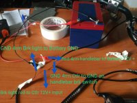
chemistry has nothing to do with where the electrons are flowing. What's more important is that your seperate battery supply's positive power can return back to it on the negative side. This is why it was recommended to connect both battery negatives together. To have the light work properly thru the brake switch is half way there. Keep that circuit as it is.

Now to tackle the issue of hooking up to the controller.

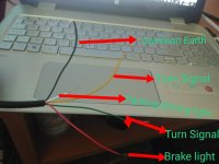
Couple things stand out... There is no "ground" at the handlebar brake switch. It's purpose is to provide a connection, or "switch" the incoming 12vdc power to the wire going to the positive side of the brake light. You have a hot side, and a switched side. The switched side becomes hot or positive voltage when the switch is made by actuating the brake lever.

With your type of brake switch wiring, the controller only needs one pin actuated or connected to your light braking system wiring.

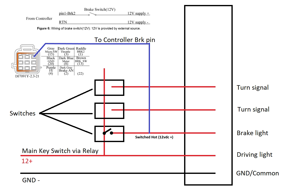
Your controller has 3 types of braking input.

1) Low brake: Grounds the controller's electronic brake signal to ground.
2) Analog brake: Variable DC input voltage.
3) High brake: 12 vdc positive input to one pin.

Each of these require different wiring.
You are using #3 option.

I do not understand about the aluminum foil conections... :roll:

I recommended this.

TommyCat said:
Just a reminder... your taking the 12vdc + line (diagrams blue wire) to the controllers High Brake signal input terminal. If I'm going by the correct manual, Pin #1 that is shared with possible motor temperature input.

TommyCat said:
Where did you terminate the blue wire on the controller? (Pin1 Brk2?)

I do not have a Kelly controller, please verify if this is the correct manual.

The manual I'm using... If this is the wrong one, please let me know!

https://kellycontroller.com/wp-content/uploads/kbs/KellyKBS-XUserManual.pdf

I'm concerned that if your wiring 2 wires, and to the wrong locations you could harm your controller. :warn:

The way I see it...

5bPKGF3.jpg
 
Could it be that light is cut in half when the brake is not engage. And when you press the brake, it will light up full and kill power to the motors??
 
the issue is the that light is full when it is not connected to the controller ... the brightness is reduced when it is connected to the controller .... I still cant figure it out .... the other issue I found is my connectors are not the default connector that come with kelly controllers .... I bought the motor and controller as a kit and the connectors are jst which the manufacturer of the motor has modified to match it, so the original manual is not working for me in this case ....
 
Any link for the kit?

Can you open up the controller and track down the correct pin that way? Finding the correct board connection and trace out to the correct wire and connector location...
 
Back
Top