Cycle Analyst V3 preview and first beta release

justin_le said:
Hey Ham, yeah as long as there is pedal cadence detected then the CA3 will continue outputting PAS power. But you can definitely set it up so that below a certain pedal effort the computed PAS output power falls down to zero watts.

In the CA3.15 and earlier firmware, the setting

PAS -> Strt Level
was the minimum amount of human watts that must be present on the pedals for the power assist to engage, so if you set this to 60 watts then light pedaling resulting in <60W of human power would mean zero output power.

The formula was basically:

Output Watts = (Human Watts - Strt Level)*(Scale Fctr)

With the CA3.2, we changed this around completely, so now Strt Level is the amount of power present with zero torque on the cranks, and then it increases from here based on your human watts:

Output Watts = Strt Level + (Human Watts)*(Scale Fctr)

In this case, if you wanted the behavior where you need a minimum amount of force on the cranks to get any output power, you need to set Strt Level to a negative value. If your scale factor is 2 W/hW, then a start level of -100 watts means that the motor power will drop off whenever there is less than 50 watts on the cranks.

Output Watts = 50W * 2 W/HW = (-100W) = 0W

So give that a try and let me know if has the behavior you are seeking. If you want the cutoff to be fast, it's good to make sure your WGain setting in the Power Limits setup menu is as high possible without being jittery, and the TrqAverage term corresponds to half the PAS poles of a full crank rotation.

Thank you! I will have a play around soon and feedback what I can make happen
 
OK so I have changed the start level for each pre set and now I can pedal gently and change gears without the motor engaged...perfect...many thanks!

My next question is to understand just what does threshold torque setting do? I get the start torque is the amount of pedal pressure that must be applied before the motor is activated from a standstill but what does the other threshold setting: "ThrshTrq" do exactly?

Thank you
 
Ham said:
OK so I have changed the start level for each pre set and now I can pedal gently and change gears without the motor engaged...perfect...many thanks!

Glad to hear this did the trick for you!

I get the start torque is the amount of pedal pressure that must be applied before the motor is activated from a standstill but what does the other threshold setting: "ThrshTrq" do exactly?
Thank you

In the case of a bottom bracket torque sensor this setting doesn't do anything other than becoming the threshold to clear a torque sensor fault if the torque signal was high when the system is first powered on. But when you have a wheel torque sensor and you don't have a cadence sensor on the cranks, then this is the torque that must be sustained while your are moving for the system to continue powering the motor in PAS mode. So Start Torque applies from a standstill, and then once vehicle speed is detected, then the lower Threshold Torque is used instead.

We needed two separate threshold settings here because people often rest their feet on the cranks when the bike is stopped, and if shifted to an easy gear that can result in more torque on the rear wheel than when you are with modest torque in a hard gear.

It's always interesting how there are so many setpoints and settings that are needed to achieve a 'natural and seamless' behavior once you start drilling into it.
 
Thanks for the reply Justin, busy as you are, it is appreciated.

The way you describe the wheel torque sensor sounds great to be honest...totally torque dependant?!...is there a way to try this out on a bottom bracket torque sensor set up?
 
Just disable the cadence sensor (disconnecting the wire(s) for that would work, for instance, if the CA doesn't have a way to not try to read one, like setting 0 poles for that sensor, etc).
 
amberwolf said:
Just disable the cadence sensor (disconnecting the wire(s) for that would work, for instance, if the CA doesn't have a way to not try to read one, like setting 0 poles for that sensor, etc).

Interesting, thank you, I will give that a go and see what happens!
 
I just had a little play with the pole count but CA only allows a low of two to be set...which is not a fun ride:)
 
I haven't had a look in the latest firmware to see what options there are, but there should be some way to disable reading the cadence sensor. If there isn't, disconnecting it is the only other option I can think of.
 
OK I will have a deeper look into the torque sensor set up and see what I can find. Physically disconnecting it means more pulling apart of wire looms as it is all part of the torque sensor wiring..I'll skip that for now as the current set up is good enough :)
 
Or you can unscrew the back of the CA and unsolder just the cadence sensor wire from the PCB. ;)

(assuming there' no setting to do it).
 
Another option indeed...not one I will be delving in to any time soon though!


Curious question would it be possible to enable the throttle to only act as regen soley but on a per profile basis
i want a profile where im power limited but also dont have a throttle outside of commuting profile but also want to keep the regen function.

from what I can see its locked to all profiles the throttle curve
 
Do you have the option of using a brake lever to control a cable-operated throttle to control regen? If so, you won't technically have a throttle, especially if you use a switch on the lever to cut power to the COT except when it is being used for braking (the same switch would tell the CA it is in braking mode, going to it's ebrake input connector).

I have a thread where I do this (though I switch between my thumb throttle and the brakelever COT rather than just disabling the COT, since I need the throttle to get started in various situations where I can't get the pedals moving first).
https://endless-sphere.com/forums/viewtopic.php?t=105460#p1542639
 
thats a lot of excess casing and wires and frankly looks like a hackup the bike its on doesn't help either lol, Nixunens solution is more elegant

also it doesn't work for people who run hydros as well
which is more common than you actually stated in the thread as they are actually quite cheap

but the point was not having a throttle at all as a toggle per profile

frankly I live in the UK and throttles on ebike are technically not legal unless you get it registered as a low powered vehicle
which takes a bunch of paperwork, specific lights, 2 vin numbers (1 stamped on frame) spending money and also going to a msva center.

I'd rather just have the throttle installed and used for convenience and the toggle it as exclusive regen if and issues arise.
if that wasn't the case I would either install a 2nd throttle to the PA regen wires or keep my current regen/backpedal regen function as its practical
 
mrbill said:
justin_le said:
1710 ohms at 100oC would mean you have a beta of about 2600, so none of the 3 options is particularly good for accurate motor temperature reporting, but you can easily make a translation table.

Any chance you could in some future release parameter-ize the NTC temperature sensor data by allowing the user to enter the resistance at 20C, beta, and optionally, the pull-up resistor value? This would allow for most or all varieties of NTC sensors.

Since I requested this enhancement to the temperature parameter configuration, I have made some further discoveries.

For several years on all of my motors I have been using these NTC thermistors with an apparent beta of 2700. (Since my calibration table included in a prior post was generated experimentally and is subject to considerable noise, I calculated beta using many different data points, and found the average closer to 2700 than 2600.) The temperature rollback range on the CA3 that I have been using for these years was 100 to 120 C, a range I thought to be on the conservative side.

Since the CA3 assumed beta was 3900, this meant that my selected temperature threshold was actually 151C to 190C ! Moreover on certain steep downhills when regenerating I saw temperature displayed as high as 154C, which corresponds to an actual temperature of 263C at the coils, where my thermistor is positioned.

Fortunately, this did not damage the motor, burn the wire enamel or degauss the magnets, but running the motor frequently up to the 150-160C range and occasionally peaking higher has had some deleterious effects. Among them:

1) Statorade appears to have "burned off" inside a well-sealed motor. I discovered this after opening the motor to check on the Statorade level when I noticed that the thermal handling of the motor had degraded. Also, the motor ran a little more noisily than before. Statorade was still present, but the fluid no longer spanned the stator-magnet gap and was thick and sludgy.

2) The bearings, especially the bearing on the freewheel plate, have become dry and slightly rough before their time, necessitating replacement.

In addition to my request that the CA3 allow the user to enter NTC thermistor beta directly so that one can observe a direct reading of the actual temperature inside the motor, I have a question: What is the maximum operating temperature of Statorade, did it get too hot inside my motors and "burn off" or might I still have a leak somewhere?
 
I put several ml of statorade in a muxus 3k motor a few years ago. The motor has never seen more than 90c since. I noticed the last time I rode in the heat that it seemed to get up to 70c right away. It didnt do that last summer. So I put about 4ml in it yesterday while watching the no-load current. Somewhere between 3 and 4 ml is when the no-load current started to increase indicating to me that there was some drag from the statorade in the gap. This is how I did it the first time. So it stands to reason the liquid went somewhere over the last few years with way less heat than your motor. It must evaporate or soak into something in the motor.
 
Question to Justin, or someone else who have facts. :)

What is fastest PAS ramp up value? I asking because I would like fastest response with Erider. I feel too much lag with 10V/sec. For example if I need to lighten the front end to cross the obstacle, assist reacts far too slowly. I raised PAS ramp to 30V/sec and it feel little slower, so I raised ramping to 99.99V/sec and then it was sooo sluggish. I even noticed huge difference when I looked throttle output voltage, ramp up was really slow compared to 10V/sec. So what is fastest value and why ramping speed start to slowing as higher values and why, is it hardware limitation or what?

I know there is throttle ramping in controller but with throttle I get faster respose, so I thknk that's not what slow things down.
 
higher numbers *should* give faster ramping. 99v/second means it should increase by 99 volts each second, so a 5v change would take less than 1/20th of a second.

Most controller throttle inputs are only around a 3-4v range from zero to full throttle, so as long as you have the CA setup to output essentially the exact range your controller responds to, it will ramp from zero throttle to full throttle in even less time, something around 1/28th of a second, I think it would be, or less.

My SB Cruiser trike, using I think v3.14 firmware, responds essentially instantly to either throttle or the cadence-PAS, using 99v/sec for all the ramping settings.

If your controller isn't responding to the input that quickly, it may have ramping of it's own. What happens when you connect your throttle directly to the controller, and flick the throttle from zero to full in as short a time as you can manage?
 
I will refine a little more. Firmware is 3.2b3. If I select pass through or torque (A) mode for throttle, I got huge power burst kick everytime I start to pedal, doesn't matter if pas up ramp is 0.5V/s or 10V/s. This burst last maybe half second.
With Power (W) throttle mode I get sophisticated behavior, no bursts or any dangerous behavior. But pedal assist response is laggy with small under x3 torque assist levels, if I use x5 level (5W/hW) which is five times my pedal effort, throttle out voltage rises much faster compare x2 level and assist reaction time is much quicker, but also I get too much more assist than I needed.

I'm bit confused, should assist level affect to pas ramping speed? How do I get fast pas up ramping with lower assist power? And why I still got power bursts, firmware history clearly say power burst issue is fixed. I was fool and trusted that issue is fixed, so I dared to try throttle pass through mode and I almost fell off from the bike. Instant 5kW kick nicely when you are not prepared.
 
mrbill said:
Since the CA3 assumed beta was 3900, this meant that my selected temperature threshold was actually 151C to 190C ! Moreover on certain steep downhills when regenerating I saw temperature displayed as high as 154C, which corresponds to an actual temperature of 263C at the coils, where my thermistor is positioned.

Fortunately, this did not damage the motor, burn the wire enamel or degauss the magnets, but running the motor frequently up to the 150-160C range and occasionally peaking higher has had some deleterious effects. Among them:

1) Statorade appears to have "burned off" inside a well-sealed motor. I discovered this after opening the motor to check on the Statorade level when I noticed that the thermal handling of the motor had degraded. Also, the motor ran a little more noisily than before. Statorade was still present, but the fluid no longer spanned the stator-magnet gap and was thick and sludgy.

2) The bearings, especially the bearing on the freewheel plate, have become dry and slightly rough before their time, necessitating replacement.

In addition to my request that the CA3 allow the user to enter NTC thermistor beta directly so that one can observe a direct reading of the actual temperature inside the motor, I have a question: What is the maximum operating temperature of Statorade, did it get too hot inside my motors and "burn off" or might I still have a leak somewhere?

Hi Folks:

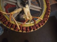
I took apart another identical motor that had also been run into high temperatures and discovered that it, too, appears to have less Statorade in the stator-magnet gap. While both motors were well-sealed, using a formable gasket of the type used to seal oil pans with automobile engine or transmission blocks, with this second motor it appears that some of the Statorade has wicked up into the coils and the wiring. I did not see any liquid having wicked to the end of the wiring outside of the motor, but this wicking may have soaked up enough to leave the gap starved of fluid.

wickingStatorade.jpg

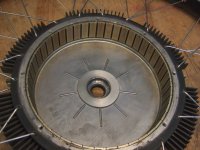
At the magnets I see some remaining Statorade, but I do not think it is enough to bridge the stator-magnet gap.

remainingStatorade.jpg

I'm guessing that what remains on the magnets is about 2 ml. Please feel free to confirm or correct my estimate. (The stator width of this motor is 35mm.)

My notes recorded that I inserted 5 ml of Statorade into this motor approximately 13k miles (21000 km) ago.

I also discovered that both bearings were relatively dry and turning with some roughness. The bearing on the brake rotor side had noticeable play.

I've decided to replace both bearings and add 5ml of Statorade (7ml total), resulting in about 2.5ml more than I need, but I'm hoping this will keep the motor running cooler for longer and increase the life of the bearings at the expense of slightly reduced efficiency.

Any other advice is appreciated.
 
mrbill said:
mrbill said:
Since the CA3 assumed beta was 3900, this meant that my selected temperature threshold was actually 151C to 190C ! Moreover on certain steep downhills when regenerating I saw temperature displayed as high as 154C, which corresponds to an actual temperature of 263C at the coils, where my thermistor is positioned.

Fortunately, this did not damage the motor, burn the wire enamel or degauss the magnets, but running the motor frequently up to the 150-160C range and occasionally peaking higher has had some deleterious effects. Among them:

1) Statorade appears to have "burned off" inside a well-sealed motor. I discovered this after opening the motor to check on the Statorade level when I noticed that the thermal handling of the motor had degraded. Also, the motor ran a little more noisily than before. Statorade was still present, but the fluid no longer spanned the stator-magnet gap and was thick and sludgy.

2) The bearings, especially the bearing on the freewheel plate, have become dry and slightly rough before their time, necessitating replacement.

In addition to my request that the CA3 allow the user to enter NTC thermistor beta directly so that one can observe a direct reading of the actual temperature inside the motor, I have a question: What is the maximum operating temperature of Statorade, did it get too hot inside my motors and "burn off" or might I still have a leak somewhere?

Hi Folks:

I took apart another identical motor that had also been run into high temperatures and discovered that it, too, appears to have less Statorade in the stator-magnet gap. While both motors were well-sealed, using a formable gasket of the type used to seal oil pans with automobile engine or transmission blocks, with this second motor it appears that some of the Statorade has wicked up into the coils and the wiring. I did not see any liquid having wicked to the end of the wiring outside of the motor, but this wicking may have soaked up enough to leave the gap starved of fluid.

wickingStatorade.jpg

At the magnets I see some remaining Statorade, but I do not think it is enough to bridge the stator-magnet gap.

remainingStatorade.jpg

I'm guessing that what remains on the magnets is about 2 ml. Please feel free to confirm or correct my estimate. (The stator width of this motor is 35mm.)

My notes recorded that I inserted 5 ml of Statorade into this motor approximately 13k miles (21000 km) ago.

I also discovered that both bearings were relatively dry and turning with some roughness. The bearing on the brake rotor side had noticeable play.

I've decided to replace both bearings and add 5ml of Statorade (7ml total), resulting in about 2.5ml more than I need, but I'm hoping this will keep the motor running cooler for longer and increase the life of the bearings at the expense of slightly reduced efficiency.

Any other advice is appreciated.

There's a couple of assumptions I'm going to make sure because I don't have a hub motor.

1) the bearings are located more centrally. Statorade won't affect bearing performance as it's strictly a magnetic/ferromagnetic fluid. As a result, it'll stick to the outer walls of your hub

2) other users here have noticed decreased statorade overtime,. Seems consistent with your experience

3) you'll likely need to replace your bearings
 
Dear community,
I have 4 cycle analyst devices mounted on 4 bicycles, I did the 3.2B3 upgrade from 3.14 on one bike to test, and I enjoyed the new features so I decided to do the upgrade on the 3 remaining bicycles.
Unfortunatly 2 of 4 are having a problem with speed reading, exactly as described by Dartman few post ago.
My configurations are Grinfineon controlers, CA DP V3 bought with 3.14 firmware, Nine continent motors (different flavors some are more than 10 years old). Speed is read though hall sensor in the motor.

So I decided to do further tests to understand my speedo problem on one bike:
- Speedo setup menu is seeing the sensor on 3.2B firmware (little arrow, up/down while moving the wheel)
- 3.2bx are not working.
- 3.15 is not working.
- 3.14 is working.
- I reset parameters few times without success

I read later that speed acquisition algorithm has evolved beetween 3.14 and 3.15, and 3.2B is probably develloped on 3.15 base.

Then the bike was connected to a scope to understand why my pulses were not seen by the CA :
No noticeable noise, in static or when the wheel is moving.
Low Level is 0.315V, high is 5.050V measured with my Fluke.
I also compared with the other working bicycle : low is 0.025V, high is 5.150V.

Could it be my low level at 0.315V that causing the problem ?
And if yes, why a firmware revision change the low level detection : is it an analog input ?
 
lightrush said:
Just tried the 3.2b2 today with my Erider-based PAS setup and I have to say - after so many years we finally instant torque from standstill! I first used a CA to control my system in 2016 coupled with a Thun BB. New torque sensing BBs like the Sempu T2, then T4 improved responsiveness. So did added features in the CA. I had managed to dial-in the current iteration of my system to have a near-instant torque by carefully adjusting various thresholds in the system to trim delays. The result was decent but it still required some 5-20 degrees of rotation before engagement. NO MORE! I almost teared up. :lol:

I'm jealous. I downloaded the latest solar firmware looking forward to having the same result - but for some reason the 36 pole Erider settings haven't been added..... :cry:

@justin_le: Please, please can you add the Erider 36 pole settings to the solar firmware also?

Thanks in advance.
 
lightrush said:
SolarFreak said:
@justin_le: Please, please can you add the Erider 36 pole settings to the solar firmware also?

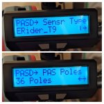
The ERider_T9 setting uses 36 poles.

That's correct - as I said. It's missing in the solar version of the firmware & custom max is 32.
 
Back
Top