
ElectricGod
10 MW
This is a test of an interesting idea. Excessive cooling...
That 7kw+ won't be peak...that will be continuous.
Mosfets can handle a ridiculous amount of current, if you can keep them cool. Whatever the die limit is for the mosfet, that's really how much current it can handle...aka 100 amps or 180 amps or whatever. There are a few limiting factors. For example the legs on a TO-220 mosfet can't deal with more than 75 amps. So no matter what the die limit is of the mosfet, you really can't get more than 75 amps out of any TO-220 mosfet. The mosfets legs will burn out or rather get so hot they will cause the mosfet to overheat. AKA leg limits and cooling are the BIG limiters to any mosfet.
The TO-220 75 amp leg limit is still a LOT....gobs...oodles...loads! In a 12 fet controller...that's like 300 phase amps...if all you have to think about is the 75 amp leg limit. Reality is obviously a bit less than this.
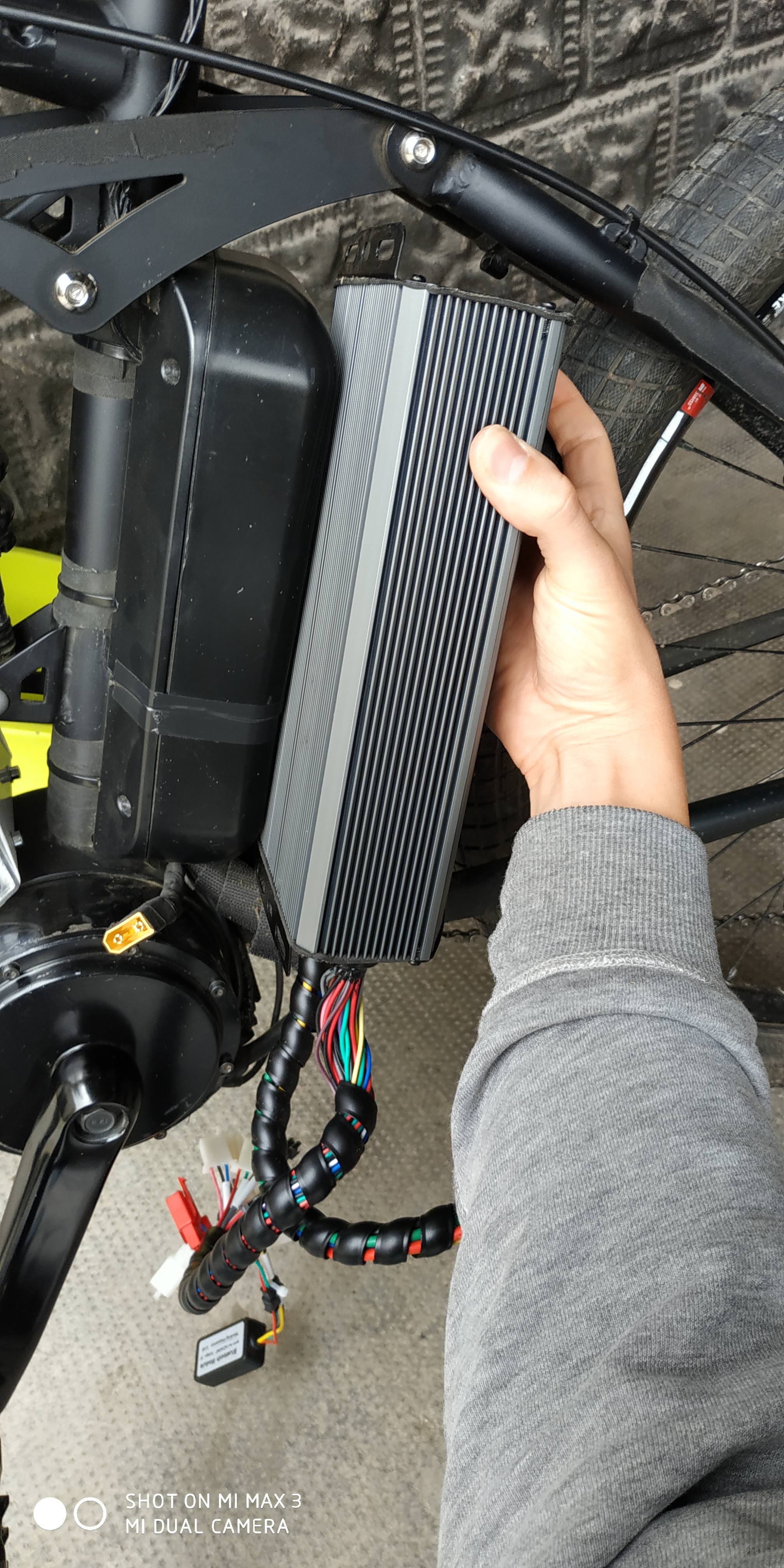
It's silly to imagine 300 phase amps coming from a 12 fet controller. BUT you can get somewhat closer to it than the 4-5kw continuous I typically see from 12 fet controllers after I mod them. What's needed is making all the power busses very stout and as close to the mosfet legs as possible. Also the mosfets need to be kept cool so they can be massive current switches. Short legs on the mosfets...as short as they can possibly be helps with this. And of course loads of heat sinking. Typical controller shells are designed for practical size instead of maximum heat sinking.
1. A typical 12 fet controller can't conduct sufficient current to get remotely close to 7kw. I need larger shunts. These are 12 awg. All I care about is keeping the total shunt resistance at 1.25 mOhms so the the MCU can read current reliably. These are about 6 mOhms each so 5 in parallel is 1.2 mOhms...close enough. I think I might get away with 6 in parallel. I did an experiment some time back with 12 awg copper wire in place of the shunts. The MCU had issues at very low current levels and would stop running the motor. Get the motor going a little bit so current draw could get to about 10-20 amps and it ran just fine. I was at about .5-.75 mOhms with straight copper in place of the shunts.

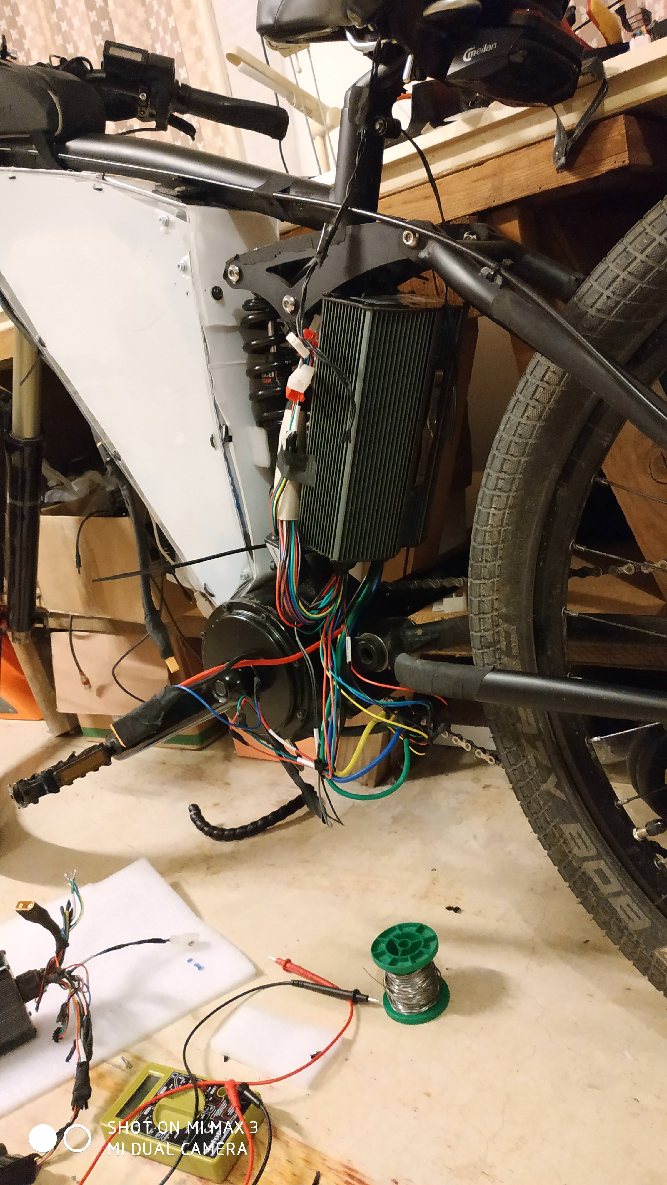
2. All the current paths need to be beefed up. In a PV 12 fet, they already have .5mm of added copper on all the main traces. I intend to beef them up with some solid copper wire and extend the wire to the actual mosfet legs. Currently the phase and power traces extend to the mosfets with some added solder.

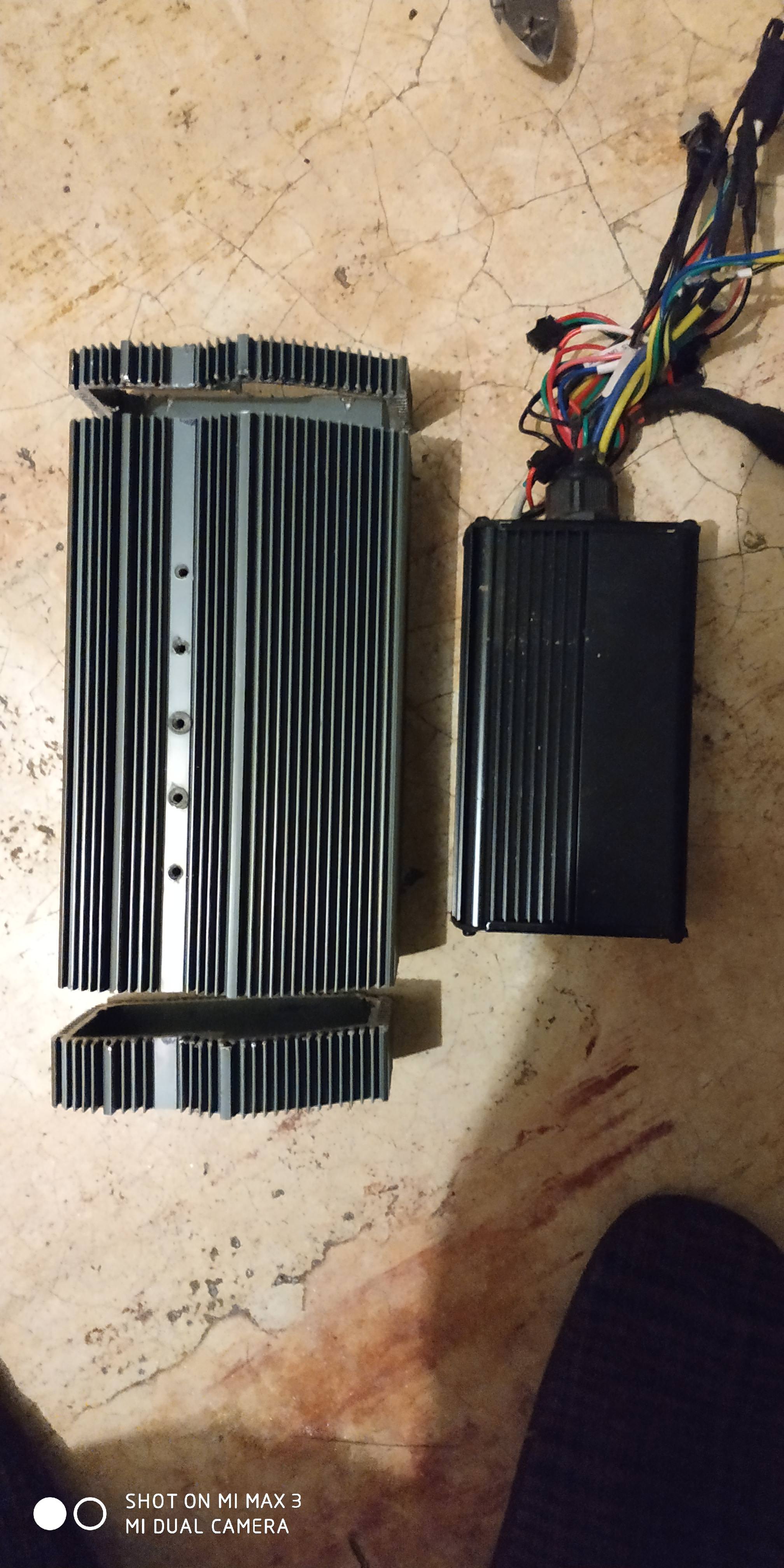
3. The internal heat spreader is fine for internal, but the shell needs a lot of help. Imagine adding a second heat spreader on the outside of the controller that then extends to LOTS more heat sinking. I'll be using 1/4" thick 6061 for the external heat spreader and for extending to a larger heat sink.

4. The secondary heat sinking will be comprised of 2 CPU heat sinks. I doubt I'll need the fans since lots of direct airflow will happen while moving. In an active airflow path, this ought to provide a LOT of cooling. I'll mount them something like this. With the vertical arrangement, a fan between them will pull air in one heat sink and out the other one...if I need added cooling.


The rest will be what I typically do to a 12 fet to get it to work at 4-5kw continuous.
10 awg phase and battery wires being the big thing still needing done. The controller already has top tier TI mosfets.
What the controller is actually capable of...well that we will see! I built up a 12 fet controller for a friend in the UK. He is consistently seeing 6kw since his is mounted directly to a thick piece of steel in his battery box. His controller temps are rarely more than air temperature.
More to come soon...
That 7kw+ won't be peak...that will be continuous.
Mosfets can handle a ridiculous amount of current, if you can keep them cool. Whatever the die limit is for the mosfet, that's really how much current it can handle...aka 100 amps or 180 amps or whatever. There are a few limiting factors. For example the legs on a TO-220 mosfet can't deal with more than 75 amps. So no matter what the die limit is of the mosfet, you really can't get more than 75 amps out of any TO-220 mosfet. The mosfets legs will burn out or rather get so hot they will cause the mosfet to overheat. AKA leg limits and cooling are the BIG limiters to any mosfet.
The TO-220 75 amp leg limit is still a LOT....gobs...oodles...loads! In a 12 fet controller...that's like 300 phase amps...if all you have to think about is the 75 amp leg limit. Reality is obviously a bit less than this.
It's silly to imagine 300 phase amps coming from a 12 fet controller. BUT you can get somewhat closer to it than the 4-5kw continuous I typically see from 12 fet controllers after I mod them. What's needed is making all the power busses very stout and as close to the mosfet legs as possible. Also the mosfets need to be kept cool so they can be massive current switches. Short legs on the mosfets...as short as they can possibly be helps with this. And of course loads of heat sinking. Typical controller shells are designed for practical size instead of maximum heat sinking.
1. A typical 12 fet controller can't conduct sufficient current to get remotely close to 7kw. I need larger shunts. These are 12 awg. All I care about is keeping the total shunt resistance at 1.25 mOhms so the the MCU can read current reliably. These are about 6 mOhms each so 5 in parallel is 1.2 mOhms...close enough. I think I might get away with 6 in parallel. I did an experiment some time back with 12 awg copper wire in place of the shunts. The MCU had issues at very low current levels and would stop running the motor. Get the motor going a little bit so current draw could get to about 10-20 amps and it ran just fine. I was at about .5-.75 mOhms with straight copper in place of the shunts.
2. All the current paths need to be beefed up. In a PV 12 fet, they already have .5mm of added copper on all the main traces. I intend to beef them up with some solid copper wire and extend the wire to the actual mosfet legs. Currently the phase and power traces extend to the mosfets with some added solder.
3. The internal heat spreader is fine for internal, but the shell needs a lot of help. Imagine adding a second heat spreader on the outside of the controller that then extends to LOTS more heat sinking. I'll be using 1/4" thick 6061 for the external heat spreader and for extending to a larger heat sink.
4. The secondary heat sinking will be comprised of 2 CPU heat sinks. I doubt I'll need the fans since lots of direct airflow will happen while moving. In an active airflow path, this ought to provide a LOT of cooling. I'll mount them something like this. With the vertical arrangement, a fan between them will pull air in one heat sink and out the other one...if I need added cooling.
The rest will be what I typically do to a 12 fet to get it to work at 4-5kw continuous.
10 awg phase and battery wires being the big thing still needing done. The controller already has top tier TI mosfets.
What the controller is actually capable of...well that we will see! I built up a 12 fet controller for a friend in the UK. He is consistently seeing 6kw since his is mounted directly to a thick piece of steel in his battery box. His controller temps are rarely more than air temperature.
More to come soon...


 f:0
f:0


