Ebike axle wiring

MarkJohnston

10 kW
Joined
Mar 25, 2021
Messages
620
Hello

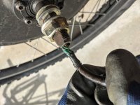
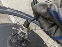
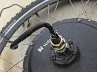
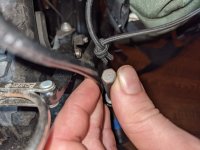
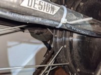
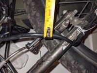
My ebike axle wiring is cracked as seen in the pictures. So far it doesn't look the wires are touching. However I can see the insulation is starting to crack in multiple places on the hall wiring. IMO before I start getting problems. I am especially worried that the wheel could suddenly go into reverse while at 40MPH. :shock:

I think it cracked in the first place because the axle is vibrating against the insulation but I am not sure why they would design this so crappy. I have been very careful when changing flats to make sure to lay it down non wore side.

For now I just put electrical tape over it. Thankfully I live in LA and it barely rains here.but I'd water gets in here I don't think it would be good. Please tell me what I should do. Also I don't have the time or tools to overhaul the hub and fix the wiring so please keep that in mind. I'm about to go on a tour with this ebike and want this fixed!!!
 

Attachments

  • PXL_20210818_225111202.jpg
    PXL_20210818_225111202.jpg
    268.7 KB · Views: 676
  • PXL_20210818_225121537.jpg
    PXL_20210818_225121537.jpg
    269 KB · Views: 676
  • PXL_20210818_225241674.jpg
    PXL_20210818_225241674.jpg
    219.9 KB · Views: 676
y MarkJohnston » Sep 17 2021 5:55am

ZeroEm wrote: ↑Sep 07 2021 10:35am
I'm switching my setups to the L1019 Plugs. It would be a no brainer to just buy a pair. you would have the cable and the plugs.
It's $60 for grin tech L1019. That includes male, female, and ext

I'm only doing it so I can swap motors and wheels around for some test. What I remember is 12ga for the phase wires. Have a leafmotor on my trike that needs to be pulled off. Need to change the tempter sensor and clean the motor up and put one of the L1019 pigtail on it. will see if I can cram it in.

Knowing what I know now, when I first put the motor on would have just made solid connections. Have not had the motor off in 2.5 years. Thinking about it the L1019 maybe just a trend. Some may want the bigger wires just outside of the axel.
 
Might be best to go from a smaller wire at the axle to a larger wire right after. Saves people with routing the wire through the axle and soldering onto the windings. But if the existing wire is damaged, then you either squish the wire back and heat shrink it, or your lucky and have enough slack of wire inside the motor to bring the damaged wire more out and snip it off and replace.
 
I'm watching you and see what you get away with. Realize you have no choice than to replace your wires. Just stating that Grin gets their wire bundle thru the axel holes.

Wonder how the Axel holes vary in sizes between motors? Wonder if the Leafmotor's Axel hole is smaller or larger compared to others?

I'm not pushing adding larger wires if not needed. It would be a by use case. If I could get 12g Phase wires thru axel hole i'm good. I'm one of them 72V'ers who get plenty of watts in the motors.

by markz » Sep 17 2021 1:51pm

Might be best to go from a smaller wire at the axle to a larger wire right after. Saves people with routing the wire through the axle and soldering onto the windings. But if the existing wire is damaged, then you either squish the wire back and heat shrink it, or your lucky and have enough slack of wire inside the motor to bring the damaged wire more out and snip it off and replace.
 
The BMC motor I set up for somebody a few years ago had heavy gauge, solid magnet wire through the axle bore. It creeped me out a little, but it has worked all this time.
 
Check out icecube57 and what he did with his mxus 45H "3kw"
He used the stock phase wires and went to 8 or 10awg wire right at the axle exit to the controller.

For the rest of us with mangled wires at the axle exit the only thing to do is replace the wire.

There is not enough slack in the wires inside the motor to pull the wires out and cut off the damaged part.

Best to leave about 2-3" of the stock phase wires from the winding solder joint, so you can wrap it around your new wire. Otherwise you'll need a big soldering iron to heat up the phase wire bundle and once the winding solder gets liquid you get springy action and strands of winding wire become detached and is hard to get back in place. All I did was take locking pliers to squish the windings together and lots of solder.
 
LewTwo said:
MarkJohnston said:
It doesn't say exactly how thick the wire is to fit though the axle bore.
See the Higo Drawing. It says 9mm but as I stated earlier the one I have only measures about 7.8mm.

HiGo L1019 Connectors and Cables (1).pdf
8mm is huge!!! My wire says 3x1.5 mm^2 +5x.2mm^2.
 
markz said:
Check out icecube57 and what he did with his mxus 45H "3kw"

Best to leave about 2-3" of the stock phase wires from the winding solder joint, so you can wrap it around your new wire. Otherwise you'll need a big soldering iron to heat up the phase wire bundle and once the winding solder gets liquid you get springy action and strands of winding wire become detached and is hard to get back in place. All I did was take locking pliers to squish the windings together and lots of solder.

Wouldn't that result in a double connection? I only have a small soldering iron. But I do have big soldering tips.
 
I think I need to get on this right away. I need to fix this cut wire at the axle. I checked the wire and the small hall green wires insulation has peeled away substantially. It's about to touch the small black hall wire!!

I noticed that now there is an open throttle situation a lot. I'll turn the throttle and LET GO but it'll keep going by itself!!! Thankfully I have a brake sensor cut off. Maybe the throttle itself is causing this problem. It's coming off the handle bar! See the picture.

Should I even ride the bike? What's the worse thing that could happen if those wires touch? Should I just unplug the hall sensor and go sensor less until the part arrives? Could I potentially damage something here?
 
Any time I hit a big bump and the bike is running by itself , i.e. an open circuit, then suddenly it stops! Honestly seems like something is loose inside the LCD, or it's the axle wiring slash/cut/

I forgot to post the picture of the throttle. Seriously, some weird stuff. I don't want to burn anything out!
 

Attachments

  • PXL_20210919_033539830.jpg
    PXL_20210919_033539830.jpg
    189.7 KB · Views: 1,160
Might be cruise conrtol, mine engage at the wrong time, it was weird at first but you get used to it.

When troubleshooting, its best to cross off the easy stuff first and systematically go through everything.
Could be as simple as some wires in the bundle of unused wires that you are not using are touching.
I don't like having a bunch of unused wires, if someone made a cheap affordable modular controller like they computer industry does modular psu's. That'd be cool, but you dont want a bunch of connectors exposed to the elements either.
 
yes score another point for front hub motor but then take one away again cos they just not cool :mrgreen: only joking, think markz motor takes the win for wire carnage :bolt: hope it didn't short out much and you test phases and halls before rewire
would not ride anymore till fixed MJ looks like you lucky not to have shorted something already :bolt: and it running away could get dangerous I liked the chuck a blob of silicon on it solution, but looks like way past that now if connectors getting that hot something not right prob time for rewire anyway loose that crappy 5 strand wire as that not helping heat issues xt connectors and solder usually fine I like to splice solder and shrink wrap my phase wires no probs so far i leave small amount extra wire so I can do punctures as others have suggested , but could use strange tube that can be changed with wheel on is called gaadi double ended tube lol ,46040.jpg
if was running mega power then i would go for be crimped like you said to handle thick guage wires , how many amps you running did see large controller with 2 pad locks can't be to careful now days can ya 8) could use one of these images.jpegsupport pannier bag off wires, put another bend in using vice drill out axle hole a bit and mount upsidedown :bolt:
invest in left hand thumb throttle is worth it
 
I just emailed grin tech about their L1019 cables. The lady said they can't do custom wire gauges even though on their website it says they CAN. Sheesh :x

Also do I need to put on a metal stress relief on the new cable? The stock cable has one but I have no idea as to what purpose it serves.

This is gonna be hard to solder. I can already tell. Soldering is not my forte. I just hope I don't damage anything
 
Yeah you got to be in the mood, the right state of mind to work on ebikes in any in-depth manner.
Lacing a wheel is the ultimate in patience and Zen

Just remember to mark the cover plate/magnet ring so the cover plate goes on the same way.
Take off the bolt and washer on the disk brake side.
Take off the cover plate bolts.
Hit the non disk brake sides axle to pop the stator out
Replace wire

Or be lazy and snip off the wire at about the 20" mark, take off the insulation, pinch the stray wires into the same wire, then heat shrink each wire. A step up from that lazy method is to buy double wall heat shrink. There is no intermediate step, either lazy method or in-depth method.
 
markz said:
Yeah you got to be in the mood, the right state of mind to work on ebikes in any in-depth manner.
Lacing a wheel is the ultimate in patience and Zen

Just remember to mark the cover plate/magnet ring so the cover plate goes on the same way.
Take off the bolt and washer on the disk brake side.
Take off the cover plate bolts.
Hit the non disk brake sides axle to pop the stator out
Replace wire

Or be lazy and snip off the wire at about the 20" mark, take off the insulation, pinch the stray wires into the same wire, then heat shrink each wire. A step up from that lazy method is to buy double wall heat shrink. There is no intermediate step, either lazy method or in-depth method.


Thanks markz.thankfully no spoke removal is necessary there. Thank the ebike gods for that.

Lazy method will not work because the wire is ruined right inside the metal axle part. In depth only. It's fine.

I'M HAVING A DIFFICULT TIME finding a REPLACEMENT CABLE. :x why the heck is grin trying to sell me a PVC jacketed wire when I really need a RUBBER jacket?! If these things tend to get sliced so easily then why o why.

Seems to me that the grin L1019 is too thick. It's 8 mm diameter and mine is a bit smaller. Markz can you send me the link to where you got your long 6 ft+ motor/ controller all in one cable on hobby king?

I think my cable diameter is smaller. Probably 7 mm. Here is a picture of the wire information printed on the cable and me holding an 8mm Allen T wrench for a eyeball comparation. The axle bore opening/slot/ clearance looks really tight.
 

Attachments

  • PXL_20210921_063531078.jpg
    PXL_20210921_063531078.jpg
    299.3 KB · Views: 1,105
  • PXL_20210921_063551725.jpg
    PXL_20210921_063551725.jpg
    278.1 KB · Views: 1,105
As far as I know (If i'm wrong correct me) Grin purchases their L1019 connector molded on the cable. So they are running the cable thru the Axel themselves. Not saying it's easy. Bought a used edge motor from billvon he ran one of these L1019 cables thru the Axel. That is why I want to upgrade my controllers and motors with the new connector. If not will straight wire them. There is always Magnet wire, like LFP and Chalo. :shock:
 
I've never done an all in one cable before.

I bought a KT display kit once that had the stupid all in one motor cable.
That connector is probably different then the one Grintech sells.
The connector was not strong, would bend and deform when you'd undo the connector which was just friction fit. Then if you undid it at an angle it would stretch the connector even more, loosening the cheap plastic and making it deform even more over time. I could not see the alignment line so I was always guessing when plugging it in, kind of like what I do everyday with the Satiator ST-3 plug, but I am just to lazy to go to the art store for some white paint.

The last thing I did with my motor was a week ago and just got some wire I already had which was 14/2 from Home Depot, opened up the motor, snipped off the sense wires inside the motor, and cable tied them out of the way to the stator metal. Then I took out the old wire, and put in new wire. Investigated the winding to phase wire connection which had a high heat sleeve on it but they put liquid electrical tape on it so I gave up and just soldered the new wire to the old wire which I left 1.5" from winding. Wrapped old 1.5" stripped wire around the new wire and layers upon layers and another layer for good measure, heat shrink with the added touch of electrical tape to cap the end of the open heat shrink, then separated the securement of those connections by mini zip ties.

Years ago when I did the MXUS 45H "3kw" hub motor, I used Teflon PTFE wire that I bought from a guy in California which I can't find his website anymore, but he sold guitar stuff like knobs and potentiometer and stuff like that. The wire was stiff, coarse strands,, stiff strands, slick outer insulation, stiff outer insulation and it was a real B! to put through axle. That I needed my Weller 140W soldering iron to solder the Teflon PTFE wire to the windings.


Markz can you send me the link to where you got your long 6 ft+ motor/ controller all in one cable on hobby king?
 
ZeroEm said:
If not will straight wire them. There is always Magnet wire, like LFP and Chalo. :shock:

Ok. So straight wiring would mean going to home Depot and getting 12 Guage wire for the phases and much smaller wire for the halls? Then I would run each wire though the bore 1 at a time and make sure to leave them WIRES LONG with tons of slack to change a tire / true wheel/ fix broken spoke. Also rubber around the axle part?

What is magnet wire?
 
This thread has lots of relative info:
https://endless-sphere.com/forums/viewtopic.php?f=2&t=24547&p=355535&hilit=+10awg+9c+upgrade#p355535
 
Have been thinking out loud. Not trying to talk anyone into anything. Need to run larger wires thru my axel first. Would not try to do a wire at a time. I would try to use a fish wire to pull with and stagger the wires enough so the thickness would ramp up. Doing it myself would teach me.
 
You need to try several different methods and it all really depends on the stiffness of the wire.
The first wire is easy, the second wire gets a little trickier and the third wire is tough.
Put the sense wires in first.
If you fish the wire through the axle, there will be a bump where you attach the metal picture hanging wire, that could scrape the insulation off the other wire. A fishing line would be more useful, maybe $10 for a beefy fishing line say 50lbs, and wrap the line around a screw driver to pull it. If you can get the wire to the 90 degree bend, then needle nose pliers to get it and bend it then add pressure to the other end pushing it down and pulling with pliers.
You name the method, do it
try it

ZeroEm said:
Have been thinking out loud. Not trying to talk anyone into anything. Need to run larger wires thru my axel first. Would not try to do a wire at a time. I would try to use a fish wire to pull with and stagger the wires enough so the thickness would ramp up. Doing it myself would teach me.
 
use a bit of tyre talc on wires should make sticky bits when pulling wire through much easier :mrgreen:
 
Shoot. I finally bought a metric tape measure. My wire diameter measures 6mm. The grin tech L1019 is 8mm total diameter. Is squeezing that in the axle bore going to f up the wire ?

Also the grin tech one is a locking anderson. it is Pte Teflon all that. Also it's rated to handle 187 degrees Fahrenheit. But my crimp connectors for large phase wires from home Depot are rated 187 and melting when not exposed to open air. Maybe home Depot is lieing about their connectors? I'm just worried I'll buy the expensive grin tech cable and have it melt. The phase pins are really really close together in that. I'm not hot rodding by any means but I need good air for those phases.

My other plan is to to just chop off the bad portion of the stock cable. I have plenty of slack in it and just resolder it the best I can. But there is a stress relief in it and I have no idea how to move it up
Also a large piece of heat shrink. What I'd I cut something important? See the original pictures.

Here is a picture of wire diameter
 

Attachments

  • PXL_20210922_080328955.jpg
    PXL_20210922_080328955.jpg
    391.6 KB · Views: 950
Back
Top