
I have a bldc Q5O1 controller and am having trouble wiring my lcd 8H display to the pcb cause im.unsure on the letter codes pn the board tht it shuld b wired to i have contacted the ppl i brought it from and they sent me a manual tht is still of no assistance can any1 help?
You are using an out of date browser. It may not display this or other websites correctly.
You should upgrade or use an alternative browser.
You should upgrade or use an alternative browser.
I have a bldc Q5O1 controller and am having trouble wiring my lcd 8H display
- Thread starter KantZ90
- Start date
docw009
1 MW
KantZ90 said:I have a bldc Q5O1 controller and am having trouble wiring my lcd 8H display to the pcb cause im.unsure on the letter codes pn the board tht it shuld b wired to i have contacted the ppl i brought it from and they sent me a manual tht is still of no assistance can any1 help?
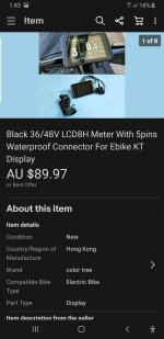
The LCD8H only works with KT controllers. Your controller does not sound like a KT model, so it will not have the same command set used by the LCD8H.
docw009
1 MW
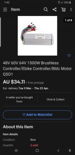
Tell the forum more about this Q501. Googling it shows nothing. Describe the bike/scooter where it's going, Voltage. Size of motor.
If the LCD8H were going to work, the controller would have a model number starting with KT-xxxxx or S-xxxxxxx.
If the LCD8H were going to work, the controller would have a model number starting with KT-xxxxx or S-xxxxxxx.
Attachments
docw009
1 MW
On the controller, maybe it doesn't use an LCD. Run it that way. Buy a inexpensive bike computer for speed/mileage.
Your LCD shows a round 5 pin connector. Did you also get an extension that connects the round pins to a flat 5 pin connector? If you do go out and buy a KT controller, you'll might have a problem connecting the round pin without that extension. You can always splice, but it wastes a good connector,
Your LCD shows a round 5 pin connector. Did you also get an extension that connects the round pins to a flat 5 pin connector? If you do go out and buy a KT controller, you'll might have a problem connecting the round pin without that extension. You can always splice, but it wastes a good connector,
TommyCat
10 kW
Please provide a LINK to your controller's information page.
docw009
1 MW
You might upload a copy of the manual that you said the vendor gave you.
TommyCat
10 kW
KantZ90 said:i am trying to wire up my 48v 1500w ebike without using any display at all
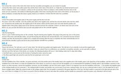
The somewhat amusing translation of the controller's wiring connectors has been the most helpful. Thank you.
In order for the controller's internal power to be actuated. You must connect the "door lock" wire to battery positive. You can do this with a key switch, or directly if so desired. It has full battery voltage, but small current.
The door lock wire is mentioned under #2 as the smaller (fine red...) RED wire of the group. And would connect to the larger battery + RED wire of the group.
Then run the learning program by connecting the indicated wires in #3. (leave non-essentials disconnected till you get the system running... IE: brake, cruise, anti-theft, ETC.
Lastly having your throttle correctly wired: RED is 5vdc +, Black is 0vdc, with GREEN the signal wire. Verify you have motor speed control.
Sounds like hall sensored operation is optional, but I would sure use it if available.
This should get you going...
Ok thx thts sounds like it could b the answer but jus curious cause ill say ive cut all the connectors off the wires and so now i have on the codes on the pcb to try identify wires by so by anychance you wouldnt happen to.b ables to tell me the codes of each the wires u jus told me.to.connext on the pcb would u?
TommyCat
10 kW
KantZ90 said:... cause ill say ive cut all the connectors off the wires
Gulp
 If so use process of elimination...
To get you started, of course you have the big wires... BLUE, GREEN, and YELLOW going to the motor's windings.
The two white wires are the learning wires.
Yellow high voltage brake, Orange(?) cruise, ETC. Eliminate each wire one by one...
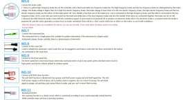
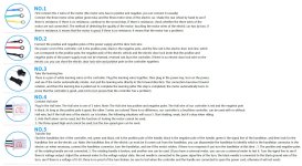
Disregarding the wire colors as shown in this illustration, here are the PCB labels to wire functions of my controller... may help a little. But I think there is little absolute conformity on labeling.
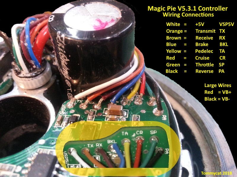
A few good pictures of your board highlighting the wire colors and labels may be helpful.
Those controllers work well. No PAS input, so if your bike had that; no more. The throttle with cruise control is better better than PAS, IMO.
From the "Manual" and the circuit board, you should be able to figure out most of the wire except for 2 or 3.
The Red and Black thick wires go to the battery. There are usually 2 smaller red wires also connected to Battery +. One for the alarm (probably not used) the other so you can put a switch between the battery and Vcc (controller power) and turn the controller off and and on. Vcc is labled on most boards always toward the back opposite side where mosfets live.
Phase wire are the 3 thick wires Y G B.
The 5 hall wires are R Blk Y G B and they will be in a row on the circuit board usually marked 5v, U, V, W, GND
All black wires and 1 of the white wires go to GND. Double check with a ohm meter/continuity tester. The throttle, 3speed, low brakes, cruise, reversing, learning and power to the anti theft all have 2 or 3 wires and one of them is ground. If you mix up the blacks (and the learning ground white) it doesn't matter.
The orange is cruise (current throttle position is locked until you touch, brake, throttle, 3 spd.
The throttle (called transfer line) has a red(4.3v), green and black all together
Any wires connected to the same pad as the Yellow Phase wire are for the alarm (you probably won't use).
The only small yellow is for brake high (you probably won't use)
The brown is for 3spd switch low (when connected to ground)
That should leave only 2 white wires and 2 blue wires to figure out.
If one of the blues is next to the brown on the board, it's usually the high of the 3 spd switch. Sometimes it's far away from the brown. The other blue is the alarm sense. You can test. If one of the blues changes the speed of the bike when connected to ground that's 3spd high.
One of the unkown whites is brake low (turns off throttle when connected to ground) the other is the learning wire that isn't connected to ground. You can safely test those.
Never cut off connectors without ID's, Just a loose piece of shrink tube around any wires that had the same connector is usually
enough to figure out everything.
Be sure to cap (hot glue?) the ends of unused wires so they don't touch something bad.
Good Luck