Right settings for regenerative charge ?

Sparfuchs

1 kW
Joined
Nov 22, 2020
Messages
305
Hello EV friends,
unfortunately i haven't found enough information about regenerative charge to be sure i wouldn't harm my battery or my controller (if this is even possible ?). I've a Sabvoton 72150 with a Mxus 3k turbo and a 20s6p battery pack with samsung 35e cells, charge current is 5A. For more details here is the battery pack link:
https://www.aliexpress.com/item/32954363991.html?spm=a2g0s.9042311.0.0.27424c4dAYzvKr
I'd like to use a thumb throttle to use the variable braking funktion.

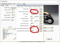
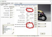
So i would really appreciate if someone could tell me what range is safe to use, or most common/effective, or what range to try out with my set up at following settings in the sabvoton software:

Slide regenerative charge current (A) ?

Slide regenerative charge speed (rpm) ?

Thanks a lot for your help.
Best regards Sparfuchs
 
Since the regen current is charging current, then if your battery has a limit to the charging current, you may want to stay within that limit. (this limit has nothing to do with your actual charger, either...just the BMS and the cells).

If the BMS has separate charge and discharge ports, then the BMS charging limit doesn't really apply (though the discharge one may, even though you're going backwards into it), and you are now at the charging limit of the *cells* for the regen limit.


You'll need to check your specific software "manual", but Regen speed limit is *usually* the fastest speed that it allows regen to start at, so that if you are going really fast and suddenly hit max regen you don't generate so much voltage that you blow up the controller or BMS.

*Sometimes* it might mean the lowest speed that regen would operate at.


Remember also that if the BMS shuts off because it detects overvoltage or overcurrent in the battery due to regen current, the voltage inside the controller will spike really fast as it has nowhere to go now, and this can blow up the FETs and stuff if it's high enough (faster speed means higher generated voltages).


Note that more current is more braking force. More current from a faster speed can be a lot more braking force.
 
amberwolf said:
Since the regen current is charging current, then if your battery has a limit to the charging current, you may want to stay within that limit. (this limit has nothing to do with your actual charger, either...just the BMS and the cells).

If the BMS has separate charge and discharge ports, then the BMS charging limit doesn't really apply (though the discharge one may, even though you're going backwards into it), and you are now at the charging limit of the *cells* for the regen limit.


You'll need to check your specific software "manual", but Regen speed limit is *usually* the fastest speed that it allows regen to start at, so that if you are going really fast and suddenly hit max regen you don't generate so much voltage that you blow up the controller or BMS.

*Sometimes* it might mean the lowest speed that regen would operate at.


Remember also that if the BMS shuts off because it detects overvoltage or overcurrent in the battery due to regen current, the voltage inside the controller will spike really fast as it has nowhere to go now, and this can blow up the FETs and stuff if it's high enough (faster speed means higher generated voltages).


Note that more current is more braking force. More current from a faster speed can be a lot more braking force.

Thanks a lot for your reply amberwolf,

how do i find out if my battery has a limit or how much that limit is ? All i know is that its a 50A BMS and Samsung 35E cells (20s6p) and a view more details the seller wrote in the description (copy of it below). But i don't know what to do with these information.

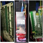
I also don't know if the BMS has separate ports so i'll just post a pic of it. Hopefully someone could tell me.1614459770210.jpg

And again, how do i know how many rpm i could take or how to find out ?

Is there a way to use a shunt or a fuse to protect my battery and my controller or how do i make sure nothing happens to them ?

It would also help a lot if you would tell me what numbers you would use or try first in my screenshot if you'd have the exact same equipment than i have ?InkedScreenshot 2021-02-27 212158_LI.jpg

Here is the copy of the battery description:

Lithium battery specification:

Battery Model:72V 21Ah
Nominal Capacity (AH) :21ah
Nominal Voltage (V): 72V
Cell Source Resistance (mΩ) :within 38mΩ
Cell Specification :Use Samsung 3500MAH Cells
Cell Combination :6-parallel 20-series

Lifecycle:more than 800 cycles
Battery Size :300*200*80*260*50*70MM
Battery Weight : About 6kgs

Charge:

Way of charge:CC/CV

Standard charge Current:5A

Max Continuous Charge Current:5A

Charge Cut-off Voltage: 84V

Cell Overcharge protection Voltage:4.2V

Charge Temperature Range :0 - 45°C

Discharge:

Max Continuous Discharge Current:50A

Peak Discharge Current:150A

Discharge Cut-off Voltage:60+/-1 V

Cell Overdisharge protection Voltage:2.75V

Discharge Temperature Range: -20 - 60°C
 
Sparfuchs said:
I also don't know if the BMS has separate ports so i'll just post a pic of it. Hopefully someone could tell me.
Discharge Temperature Range: -20 - 60°C

The battery from your link appears to have an XLR connector for charging, and separate Anderson connectors for discharging.
 
E-HP said:
Sparfuchs said:
I also don't know if the BMS has separate ports so i'll just post a pic of it. Hopefully someone could tell me.
Discharge Temperature Range: -20 - 60°C

The battery from your link appears to have an XLR connector for charging, and separate Anderson connectors for discharging.
Thanks for your reply E-HP,
so what does that mean for my settings ?
 
It means that the BMS would not be limiting current during regen, so you have to protect the battery yourself by choosing a reasonable charging current, based on the cell specs and pack configuration.
 
E-HP said:
It means that the BMS would not be limiting current during regen, so you have to protect the battery yourself by choosing a reasonable charging current, based on the cell specs and pack configuration.
But i'm realy hard trying to find out what "reasonable charging current" means or even what it does ?
I posted all information i could find above but still
can't even tell if "reasonable" is 10, 100 or 1000 because i don't know in what context this number stands to the battery pack the cells or the bms ? I know that the battery pack can be charged with max. 5A and the cells its self with: standard charge: 1,700mA/
for cycle life : 1,020mA each. But what does that mean for e braking ?
 
Sparfuchs said:
But i'm realy hard trying to find out what "reasonable charging current" means or even what it does ?
I posted all information i could find above but still
can't even tell if "reasonable" is 10, 100 or 1000 because i don't know in what context this number stands to the battery pack the cells or the bms ? I know that the battery pack can be charged with max. 5A and the cells its self with: standard charge: 1,700mA/
for cycle life : 1,020mA each. But what does that mean for e braking ?
If the battery pack's max charge limit is 5A, then that's a good reasonable limit for regen to keep the battery safe. It may not do much at that low a current, though, so if you are expecting a lot of braking power or energy recovery, you may be disappointed.

If you want to know the max charge rate for the *cells*, you multiply the number of *parallel* cells by the max individual cell charge rate, if you have both of those numbers.

Keep in mind also that a BMS like yours with a separate charge and discharge port will have the discharge FETs (which take the regen current thru them backwards) running as "diodes" rather than "switches" so any current flow thru them that way will heat them. The higher the current, the greater the heating. The longer the heating goes on, and/or the more often the heating happens, the more likely a failure is to occur. Such failures don't get reported here very often, but they do happen from time to time. One reported failure from such heating (don't know whether it was regen or simple charging thru the wrong port) actually got so hot it desoldered the FETs from the board and shorted things out inside the battery. :(

If you really need to quantify exactly what you can do with the stuff you have, you would need to open up the battery, add temperature sensors to the FETs and BMS board, close everything up again, and then use a controlled-current power supply to simulate the regen, and test to see what various levels of current actually cause for heating. Generally 70C is where stuff starts going wrong, but it can happen sooner, so I recommend keeping temperature there as low as you can.
 
Sparfuchs said:
E-HP said:
It means that the BMS would not be limiting current during regen, so you have to protect the battery yourself by choosing a reasonable charging current, based on the cell specs and pack configuration.
But i'm realy hard trying to find out what "reasonable charging current" means or even what it does ?
I posted all information i could find above but still
can't even tell if "reasonable" is 10, 100 or 1000 because i don't know in what context this number stands to the battery pack the cells or the bms ? I know that the battery pack can be charged with max. 5A and the cells its self with: standard charge: 1,700mA/
for cycle life : 1,020mA each. But what does that mean for e braking ?

to be safe you could put charge current at 6amps (6amps x 72v=432watts of regen braking)

what would electric brake phase current be? 10amps???


InkedScreenshot 2021-02-27 212158_LI.jpg
 
goatman said:
Sparfuchs said:
E-HP said:
It means that the BMS would not be limiting current during regen, so you have to protect the battery yourself by choosing a reasonable charging current, based on the cell specs and pack configuration.
But i'm realy hard trying to find out what "reasonable charging current" means or even what it does ?
I posted all information i could find above but still
can't even tell if "reasonable" is 10, 100 or 1000 because i don't know in what context this number stands to the battery pack the cells or the bms ? I know that the battery pack can be charged with max. 5A and the cells its self with: standard charge: 1,700mA/
for cycle life : 1,020mA each. But what does that mean for e braking ?

to be safe you could put charge current at 6amps (6amps x 72v=432watts of regen braking)

what would electric brake phase current be? 10amps???

--

If it helps anyone in any way, with Sabvoton controller the regen power depends on your actual speed.

I have my regen set to 200 Phase amps....
At 60-70 kmph this means about 3000W regen (40 battery amps, give or take, at 72V)
At near stop (eg stopping at red lights) the regen force is nearly non-existant, as well as battery current. Because of the tiny generated bEMF at those lowest speeds.
The motor simply does not turn fast enough (doesn't generate enough bEMF voltage) to overcome the resistance of the whole system.

If you set the regen to a low value, expect next-to-no braking force at low speeds.
If you set it high, brake very carefully when going fast.

-frankie
 
amberwolf said:
If the battery pack's max charge limit is 5A, then that's a good reasonable limit for regen to keep the battery safe. It may not do much at that low a current, though, so if you are expecting a lot of braking power or energy recovery, you may be disappointed.
hmm, that are not the best news. I thought the regenerative charge is a quite popular and common thing but now it sounds quite special to me. I thought I've a quite "normal" battery pack. So what has to be different at a battery that it works fine for regen braking ?
amberwolf said:
If you want to know the max charge rate for the *cells*, you multiply the number of *parallel* cells by the max individual cell charge rate, if you have both of those numbers.
So in my case that would be 1,700 mAh per cell x 6 parallel = 10,2mAh/0,0102 A :D i think the datasheet means 1700 mAh right ? so it would be 10,2 A..what seems more realistic to me.
amberwolf said:
Keep in mind also that a BMS like yours with a separate charge and discharge port will have the discharge FETs (which take the regen current thru them backwards) running as "diodes" rather than "switches" so any current flow thru them that way will heat them. The higher the current, the greater the heating. The longer the heating goes on, and/or the more often the heating happens, the more likely a failure is to occur. Such failures don't get reported here very often, but they do happen from time to time. One reported failure from such heating (don't know whether it was regen or simple charging thru the wrong port) actually got so hot it desoldered the FETs from the board and shorted things out inside the battery. :(
I found something on the pictures i made of my BMS that looks like the FETs you were talking about and a temperature sensor directly on them (look at pics). So its most likely that the BMS detects overheat an shuts off. But i'm afraid that doesn't work witch regen braking because if it switches off, the power still goes inside it because it can't go anywhere and heats up even more, right ?
amberwolf said:
If you really need to quantify exactly what you can do with the stuff you have, you would need to open up the battery, add temperature sensors to the FETs and BMS board, close everything up again, and then use a controlled-current power supply to simulate the regen, and test to see what various levels of current actually cause for heating. Generally 70C is where stuff starts going wrong, but it can happen sooner, so I recommend keeping temperature there as low as you can.
The battery is already in a aluminium box on my bike and it would be a load of work to get it out again. So thats not an option for now.
 
goatman said:
to be safe you could put charge current at 6amps (6amps x 72v=432watts of regen braking)

what would electric brake phase current be? 10amps???
Thanks a lot for your reply goatman,
so how did you get to 6 or 10 amps ? Is there a calculation behind it or is it just by feeling or experience ?
 
xfrankie said:
If it helps anyone in any way, with Sabvoton controller the regen power depends on your actual speed.

I have my regen set to 200 Phase amps....
At 60-70 kmph this means about 3000W regen (40 battery amps, give or take, at 72V)
At near stop (eg stopping at red lights) the regen force is nearly non-existant, as well as battery current. Because of the tiny generated bEMF at those lowest speeds.
The motor simply does not turn fast enough (doesn't generate enough bEMF voltage) to overcome the resistance of the whole system.

If you set the regen to a low value, expect next-to-no braking force at low speeds.
If you set it high, brake very carefully when going fast.

-frankie
Thanks a lot for your reply frankie,
that's a quite interesting information... even if i don't understand all of it :D
But in practice that would mean if i make sure i won't use it at more than 30 kph, i could set it to 200 phase amps without harming the batteries ? Or what settings would you recommend below 30 kph with my battery ?
 
Sparfuchs said:
goatman said:
to be safe you could put charge current at 6amps (6amps x 72v=432watts of regen braking)

what would electric brake phase current be? 10amps???
Thanks a lot for your reply goatman,
so how did you get to 6 or 10 amps ? Is there a calculation behind it or is it just by feeling or experience ?

Based on the cells used (appear to be Samsung 35E) and the datasheet, the cells have a max charge current of 2A and standard charge current is 1.7A, and 1A for better pack life. Since the pack is 6P, that would be a 12A max charge current, or 10.2A standard, and 6A if you want to keep the pack healthy.

https://cdn.shopify.com/s/files/1/0481/9678/0183/files/samsung_35e_data_sheet.pdf?v=1605015771

Realistically, damaging your battery is not a big risk. If you set regen current high, then the bike brakes harder, so while you get better braking, you won't get much regen since the bike is going to slow before you know it. If you set it low, the braking will decrease, but the bike speed will provide more regen to the battery. The settings help more for implementing regen braking to emphasize what you're trying to get out of it (braking, regen, or a balance). If you're using slide regen, then the settings matter even less. Monitoring the battery temps is probably a better way of protecting your pack, if you think you're feeding it too much power if you're really worried about it.
 
Sparfuchs said:
goatman said:
to be safe you could put charge current at 6amps (6amps x 72v=432watts of regen braking)

what would electric brake phase current be? 10amps???
Thanks a lot for your reply goatman,
so how did you get to 6 or 10 amps ? Is there a calculation behind it or is it just by feeling or experience ?

6 battery amps is safe for your pack

10 phase amps, i dont know the calculation for phase amps to battery amps but if my phaserunner is rated at 60 battery amps and 90 phase amps

432 watts is ok for regen, i like 800 watts

it was just a safe starting point
 
Sparfuchs said:
xfrankie said:
If it helps anyone in any way, with Sabvoton controller the regen power depends on your actual speed.

I have my regen set to 200 Phase amps....
At 60-70 kmph this means about 3000W regen (40 battery amps, give or take, at 72V)
At near stop (eg stopping at red lights) the regen force is nearly non-existant, as well as battery current. Because of the tiny generated bEMF at those lowest speeds.
The motor simply does not turn fast enough (doesn't generate enough bEMF voltage) to overcome the resistance of the whole system.

If you set the regen to a low value, expect next-to-no braking force at low speeds.
If you set it high, brake very carefully when going fast.

-frankie
Thanks a lot for your reply frankie,
that's a quite interesting information... even if i don't understand all of it :D
But in practice that would mean if i make sure i won't use it at more than 30 kph, i could set it to 200 phase amps without harming the batteries ? Or what settings would you recommend below 30 kph with my battery ?

Going just by numbers, if I get ~40 amps to battery at 70km/h, assuming constant phase amps, it would mean about 20amps at 35km/h .
In a linear relationship you have half the speed, you get half the amps to the battery (minus losses in the sysem).

As noted by other people in this thread, you should keep the max charge of your battery at below 12amps (2A per each cell in parallel, of which you have 6).

So I would definitely go down in the phase amps. From my 200 phase (where I would get about 20 battery amps at 30km/h) to about 120-100 phase amps (where i would expect 12-10 battery amps at 30km/h).
I don't think you would damage the battery if you shove even 20amps into it for a very short time (like some emergency braking), but I would only count on that option as an emergency, not something to do on a regular basis.

I might have missed this in the thread, do you have any monitoring software which could tell you what exactly is happening? Like a phone app for your BMS ? Or a display for the controller? Or CycleAnalyst?
This would greatly help you monitor the "ampere intake" of your battery in real time, and tell you if you can pull the regen lever a bit more and still stay within those 12 battery amps. Or whether you can set the phase amps any higher or not.

EDIT:
What i wanted to say is, if you have no way of knowing what exact battery amps you are currently getting, or if you tend to brake at "full pull", I would set the regen at 100Amps and be done with it. Just to make sure you never exceed the battery rating. At any speed you go.

IF however, you have something to keep an eye on those battery amps, OR if you tend to be very light on your regen at the top speed... You could set the regen to 200Amps (or more) and only "feather" the regen brake at high speeds.
And as you slow down, and the braking force diminishes, you could pull a little harder on that brake while still not exceeding the battery limits. And then again, it would slow you down, force becomes smaller, you pull harder again, and repeat and repeat... until you are stopped.
This however requires close monitoring (at best) or a strong discipline and carefullness at the very least...

END EDIT
 
Thank you all for your great answers.
But to be honest i feel quite overtaxed with the whole topic and all the information. So i decided to order a CA V3 to get more useful information and feel more secure. Even if i have no idea yet what i have to do with the CA to find out what settings i need. But i guess i'll find out step by step.

The CA i bought is i guess the latest version with the 8 pin waterproof connection and a handlebar switch. This one:
https://ebikes.ca/shop/electric-bicycle-parts/cycle-analysts/ca3-wp-and-mfswitch.html

but i didn't order a shunt because i thought i could get a much cheaper one than the original. Was i thinking wrong ?
Could someone tell me what shunt i really need in my case ? I'm a bit confused because the original one is not just a shunt, it also a throttle line and stuff like that.
 
Sparfuchs said:
Thank you all for your great answers.
But to be honest i feel quite overtaxed with the whole topic and all the information. So i decided to order a CA V3 to get more useful information and feel more secure. Even if i have no idea yet what i have to do with the CA to find out what settings i need. But i guess i'll find out step by step.

The CA i bought is i guess the latest version with the 8 pin waterproof connection and a handlebar switch. This one:
https://ebikes.ca/shop/electric-bicycle-parts/cycle-analysts/ca3-wp-and-mfswitch.html

but i didn't order a shunt because i thought i could get a much cheaper one than the original. Was i thinking wrong ?
Could someone tell me what shunt i really need in my case ? I'm a bit confused because the original one is not just a shunt, it also a throttle line and stuff like that.
You ordered the direct connect version, which connects to a CA compatible controller. If your controller has a compatible connector, it will use the controller's internal shunt, and one of the hall wires to determine speed.
If your controller instead has a connector for another display (e.g. TFT750C), then you may need to add a compatible connector by opening the controller and soldering one up.
 
E-HP said:
Sparfuchs said:
Thank you all for your great answers.
But to be honest i feel quite overtaxed with the whole topic and all the information. So i decided to order a CA V3 to get more useful information and feel more secure. Even if i have no idea yet what i have to do with the CA to find out what settings i need. But i guess i'll find out step by step.

The CA i bought is i guess the latest version with the 8 pin waterproof connection and a handlebar switch. This one:
https://ebikes.ca/shop/electric-bicycle-parts/cycle-analysts/ca3-wp-and-mfswitch.html

but i didn't order a shunt because i thought i could get a much cheaper one than the original. Was i thinking wrong ?
Could someone tell me what shunt i really need in my case ? I'm a bit confused because the original one is not just a shunt, it also a throttle line and stuff like that.
You ordered the direct connect version, which connects to a CA compatible controller. If your controller has a compatible connector, it will use the controller's internal shunt, and one of the hall wires to determine speed.
If your controller instead has a connector for another display (e.g. TFT750C), then you may need to add a compatible connector by opening the controller and soldering one up.

Oh sh*t..that doesn't sound that good. But i guess there is no better version if my sabvoton 72150 has no CA or Display connection right ? So whatever version i chose i'll have to solder something together to get the data the CA needs. Or is there an other Option ?
 
Sparfuchs said:
Oh sh*t..that doesn't sound that good. But i guess there is no better version if my sabvoton 72150 has no CA or Display connection right ? So whatever version i chose i'll have to solder something together to get the data the CA needs. Or is there an other Option ?

I think the CA3-DPS (non-HIGO) plus the stand alone shunt is what would work. The CA3-DPS has a speed sensor and the shunt connect to the direct connect plug, and separates out the throttle signal to the controller.

https://ebikes.ca/shop/electric-bicycle-parts/cycle-analysts/ca-sa.html
 
Back
Top