Battery won’t charge.

rick_p

100 W
Joined
Feb 16, 2021
Messages
260
Location
Los Angeles
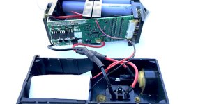
I would like to resurrect my old ebike that was working until I had a battery problem. One day I plugged in the charger and nothing, it wouldn’t go into charge mode. I unplugged the charger and checked the fuse, it was blown, so I replaced it with the same exact type and amp rating. I plugged in the charger and the charger went into charge mode for about a second, but then it almost instantly stopped charging went went back into idle mode. I knew there is circuit protection inside the battery box so I unplugged, and removed the battery pack from the case to inspect. All the wiring appears intact (no visible damage) and the circuit boards don’t have any visible signs of short circuiting. Is this a hopeless case? Meaning, is it a case of there are no user replaceable parts at this point, or is there anything else I can check? The cells were probably around midway through their life span, I was still getting around 20 miles out of a charge before the failure, so it would be nice to get this bike back on the road if I don’t have to buy a new battery for it.
 
rick_p said:
One day I plugged in the charger and nothing, it wouldn’t go into charge mode. I unplugged the charger and checked the fuse, it was blown, so I replaced it with the same exact type and amp rating. I plugged in the charger and the charger went into charge mode for about a second, but then it almost instantly stopped charging went went back into idle mode.

What do you mean that it stopped working? Do you mean the fuse blew again, or the charger just went into idle like the battery was charged?
 
It must surely be a coincidence that just two days ago, everything was fine and then you replaced both of the output connectors on the main battery leads, and then, immediately after that, the charging problem suddenly manifests itself.

My guess would be that the two wires touched at some point and blew the BMS.

Also possible that these are also the charging leads and the connectors were not properly installed.
 
E-HP said:
What do you mean that it stopped working? Do you mean the fuse blew again, or the charger just went into idle like the battery was charged?
The latter, the charger just goes into idle like the battery is charged. I double checked the new fuse, it’s still good.

AngryBob said:
It must surely be a coincidence that just two days ago, everything was fine and then you replaced both of the output connectors on the main battery leads, and then, immediately after that, the charging problem suddenly manifests itself.
This is a different bike, it’s my old bike, which I stopped riding when the battery died so I bought a new bike because pre-COVID I rode a bike to work every day, so I didn’t want to be down for too long. It was my new-ish bike that had the bad wire connection. Thankfully, the problem has not returned on that bike yet, I may have I lucked out if that is all that was wrong, but it was intermittent, so still need to give it a little more time to be sure. I’m hoping my wife will go on long rides with me if I get this one going again.
 
I did some inspection/testing last night and made a couple of interesting discoveries. Using recent lessons learned, I started looking closer at the exposed wiring and connections. I noticed that the male tip of the charger doesn’t always make a good connection with the female receptacle on the battery. However, after taping it in position temporarily and then plugging the charger in, it started charging for a few minutes and then cut itself off. I tried this a few times and got the same results, sometimes it will charge for several minutes and other times it cuts off after only a few seconds. It appears there is circuit protection that is either doing it’s job because something is shorting out, or it’s just failing. There is more testing I can do, such as making sure it’s not the charger that is failing, and I also need to make sure it’s not losing connection at the plug, taping it in place is not a viable test. Any ideas appreciated though.
 
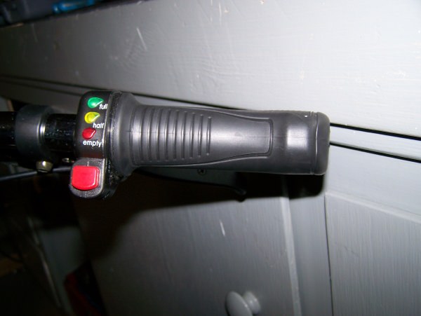
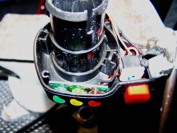
I did some additional testing. I bought another charger just to make sure the problem is with the battery and not the charger, but it is in fact the battery that has the problem. The battery isn’t completely drained, so plugged it into the bike and tried to turn it on, and the LED lights that normally indicate the amount of charge with red, yellow, and green lights, just flashed some sort of pattern in red. I’m not sure what that means exactly but I’m sure it’s similar to an error code on an LCD display. Which is more likely to cause these symptoms, a bad cell or a bad BMS controller?
 
rick_p said:
I bought another charger just to make sure the problem is with the battery and not the charger, but it is in fact the battery that has the problem.
Been there, done that multiple times.
Lest I repeat myself see my comments at the start of this thread:
https://endless-sphere.com/forums/viewtopic.php?f=2&t=110754

If there is a problem with the battery then you will need to get inside the battery ahead of the BMS and determine if you have problem with a cell string(s) or the BMS.

Which is more likely ? Toss a coin .... but if absolutely had to guess I bet on the BMS.
 
Maybe you need to try and get a direct charge to the battery with some kind of makeshift jumpers or mini alligator clips. Just carefully line up the plus and minus jumpers. This will eliminate and contact/plug issues on both sides of charging wiring. It will perhaps allow you to bypass BMS and other obstacles.. You will be charging right on to the battery. My point is that something could be frayed or torn just enough to work intermittently. If that is not the problem, then you can be sure it is the within the battery by eliminating the in between contacts. Did you use a multimeter?
 
BMS-front.jpg
LewTwo said:
If there is a problem with the battery then you will need to get inside the battery ahead of the BMS and determine if you have problem with a cell string(s) or the BMS.
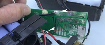
I’m inside the battery and getting 52 volts from the cells, tested at the back of the BMS (see arrows in picture below) where the cells are connected to the BMS board, but how exactly do I determine if I have a problem with a cell string(s) or the BMS? Note the crust around the solder joint at the ground wire, I can't tell if that is from moisture or acid flux.
BMS-back.jpg
RTLSHIP said:
Maybe you need to try and get a direct charge to the battery with some kind of makeshift jumpers or mini alligator clips. Just carefully line up the plus and minus jumpers. This will eliminate and contact/plug issues on both sides of charging wiring. It will perhaps allow you to bypass BMS and other obstacles.. You will be charging right on to the battery. My point is that something could be frayed or torn just enough to work intermittently. If that is not the problem, then you can be sure it is the within the battery by eliminating the in between contacts. Did you use a multimeter?
Yes, I used a multimeter, and got a readout of 52 volts, so I don’t think I need to add any additional charge to the battery. Besides, from the videos I’ve watched, charging the cells without the use of a BMS can damage the cells. Is it safe to assume the cells are fully charged if I’m getting 52 volts ahead of the CMS? If so, does this prove that the BMS is bad?

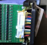
If so, note the wiring and connectors to the board below. There are part numbers on a sticker and on the circuit board itself, I searched for them online and got no returns. There are dozens of 48 volt 10 amp BMS for sale, they all have 14 wires in one connector. Mine has 14 wires too, but mine has two connectors, and the others all have the positive wire at one end and the negative wire at the other, with the rest of the wires all being white. Mine is not like that, even if you disregard the fact that mine has two connectors and lots of colors, the negative wire is not on the outside, there is a yellow wire after it. So, how would I know how to match up the wires if I bought a replacement?
BMS-wires-connectors.jpg
 
As for the number of connectors and the color coding ... some of our friends in SEA are NOT known for their consistency. What is important is the number ballance leads and that quantity seems correct.

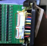
You can check the string voltages using the balance wire solder points. Between any two adjacent solder points you should have about 3.71 volts (52 volts divided by 14 parallel strings). How close should they be ??? Depends on the BMS. They should be with 0.10 volts (that is the delta voltage for active balancers).
ballance wires.jpg
I might get flamed for this:
I agree that you should not charge the battery with an typical E-bike Red/Green LED charger without a BMS in circuit.
However there are people that run their packs w/o BMS and charge them via variable power supplies or RC chargers.
 
LewTwo said:
You can check the string voltages using the balance wire solder points. Between any two adjacent solder points you should have about 3.71 volts (52 volts divided by 14 parallel strings). How close should they be ??? Depends on the BMS. They should be with 0.10 volts (that is the delta voltage for active balancers).
I got precisely 4.17 volts between each adjacent pair. Does that tell us anything?
 
It means that all of the tested cell groups are connected to the BMS well enough for the BMS to read them, and that they are all well-balanced and almost completely full.

So if it won't charge, the next point to test is the charge port pad of the BMS. This is usually marked as the C- pad. From there to the B+ pad (or the main big fat red wire on the battery cells) should read the number of series cells x 4.17v.

If it doesn't, then that means the BMS has turned off that port, or the FETs to the port are defective.

If it does have the correct voltage, then proceed to each point in the wiring that you can check between that pad and the charging connector. Wherever the voltage stops being right, is past or at the problem.
 
amberwolf said:
So if it won't charge, the next point to test is the charge port pad of the BMS. This is usually marked as the C- pad. From there to the B+ pad (or the main big fat red wire on the battery cells) should read the number of series cells x 4.17v.
I got 54 volts, which is correct I believe, because I think there are only 13 series of cells, even though there are 14 wires. Therefore 13 x 4.17 = 54.21.

amberwolf said:
If it doesn't, then that means the BMS has turned off that port, or the FETs to the port are defective.
I guess we have ruled this out.

amberwolf said:
If it does have the correct voltage, then proceed to each point in the wiring that you can check between that pad and the charging connector. Wherever the voltage stops being right, is past or at the problem.
There aren't really any places to check this other than at the charging connector itself, where I got 54 volts.

Since I had the voltmeter in hand, I decided to check all the obvious connections. One thing I found that surprised me, but may not be a sign of anything, was that I am getting 54 volts and 25 amps at the discharge port. Is that a normal amp rating or is it too high?

I'm beginning to wonder if the battery charger is kicking off not because there is a charging problem, but because the battery is full (at maximum charge) and that the problem is something else, and the reason I'm getting the blinking red light at the throttle switch/leds is because the controller is picking up on a problem and is going into a protection mode? Just to make absolutely sure there wasn't a connection problem between the battery and the controller, I checked the voltage/amperage at the power connectors to the controller, and I am getting 54 volts and 25 amps there too. Any ideas at this point?
 
I think you may have 14 s. a 14 should have 13 pins. The first one probably has to be tested against the main negative discharge. Though my old pack has 2 negative spots which give different readings. My old lifepo pack has 15 pins but it is a 48 v 15ah. But there are 16 tests that I take. The other 15 are side to side. It worked for me. Maybe you do have 13s. But that would put you at 48v resting if we assume 3.7v x 13.

Also, charging through the discharge cable is, as you suggested, not a good idea. But charging with skinny wires that way might give you a clue.
 
rick_p said:
I got precisely 4.17 volts between each adjacent pair. Does that tell us anything?
It tells us that the pack is charged.

It doesn't sound like you have a battery, bms, or charger issue.

If you've verified that the controller is getting power but is erroring out or otherwise failing to operate, I would focus on the controller itself and ancillaries. I have no idea what controller you're running or it's failure modes, but I would start by verifying all of the wiring for the throttle, brake, halls, and phase connections to ensure they're in good shape and getting power and ground to where it needs to be. Assuming all of the wiring is good, test the throttle and brake to verify voltage on the signal wires is sweeping as it should to help rule out a failed throttle or brake sensor. Assuming those are good, I'd start suspecting the controller itself.
 
that's well charged up. are you sure there aren't 14 reads. that would put you at 53 v which is too high. 4.1 x13= 53.3.

My guestimate it that you should have 3.8 x14= 53.9. Something like that.
 
RTLSHIP said:
that's well charged up. are you sure there aren't 14 reads. that would put you at 53 v which is too high. 4.1 x13= 53.3.

My guestimate it that you should have 3.8 x14= 53.9. Something like that.
The nominal, maximum, minimum and cutoff voltages vary depending on whose specification one reads for a particular cell chemistry. When a BMS is involved they are theoretical controlled by that device and the designers mood on the day he set values for the BMS control.

Voltage rages I have for LiCoO2 are: minimal 3.000, nominal 3.600, maximum 4.200
Voltage rages I have for NMC are: minimal 2.750, nominal 3.700, maximum 4.200
Voltage rages I have for LFP are: minimal 2.500, nominal 3.200, maximum 3.625 *** corrected ***
Voltage rages I have for NCA are: minimal 2.500, nominal 3.600, maximum 4.200
Voltage rages I have for LTO are: minimal 1.800, nominal 2.400, maximum 2.800

When charged to the max the voltages tend to drop a bit as the battery rest ...
more so if there is a phantom power drain (i.e. BMS).

In real world practice the desired delta between cell strings is the end to end voltage divided by the number of cell strings (14 by my count). Earlier he stated he had 52 volts end to end. Perhaps another end to end voltage reading is in order.
 
Lew Two, rick_p never stated what kind of lithium battery he has, but I was thinking it is Lithium-ion.
You bring up a good point: how can ideas be given with incomplete vital info.
 
rick_p, you should have started off by providing complete battery information, make and model m8. Picture or specs of the battery's data sticker. And battery cells make and model whist your in there. (Nice pics, but not enough of the full battery label.)
Help these poor lads out :!:


rick_p said:
The battery isn’t completely drained, so plugged it into the bike and tried to turn it on, and the LED lights that normally indicate the amount of charge with red, yellow, and green lights, just flashed some sort of pattern in red.

If this is the basis of concern... With the LED indicators similar to this type...

7yuWtaS.jpg


It's operation is determined from just a straight battery voltage input thru a series of resistors and other electronic components on a PCB to account for the different colored light LED requirements, nothing smart about it.

Typical problem of operation are from a bad or intermittent battery connector. Or some loss of full voltage to it.
You may want to take voltage readings right at the LED's PCB voltage input, and work backwards...

1nXoCne.jpg


Regards,
T.C.
 
RTLSHIP said:
I think you may have 14 s. a 14 should have 13 pins. The first one probably has to be tested against the main negative discharge. Though my old pack has 2 negative spots which give different readings. My old lifepo pack has 15 pins but it is a 48 v 15ah. But there are 16 tests that I take. The other 15 are side to side. It worked for me. Maybe you do have 13s. But that would put you at 48v resting if we assume 3.7v x 13.

Also, charging through the discharge cable is, as you suggested, not a good idea. But charging with skinny wires that way might give you a clue.

RTLSHIP said:
that's well charged up. are you sure there aren't 14 reads. that would put you at 53 v which is too high. 4.1 x13= 53.3.

My guestimate it that you should have 3.8 x14= 53.9. Something like that.

LewTwo said:
Voltage rages I have for LiCoO2 are: minimal 3.000, nominal 3.600, maximum 4.200
Voltage rages I have for LFP are: minimal 2.500, nominal 3.200, maximum 4.625

When charged to the max the voltages tend to drop a bit as the battery rest ...
more so if there is a phantom power drain (i.e. BMS).

In real world practice the desired delta between cell strings is the end to end voltage divided by the number of cell strings (14 by my count). Earlier he stated he had 52 volts end to end. Perhaps another end to end voltage reading is in order.

The cells are visibly Samsung ICR18650 = LiCoO2 = 4.2V charge voltage.
Balance leads are always n cells + 1. 13s pack = 14 balance leads.
4.17V/cell * 13s = 54V, in range of the 52V at the main leads previously reported.
It's a common 13s, 48V nominal pack.

Also, LFP should be maximum 3.6, not 4.6.
 
RTLSHIP said:
Lew Two, rick_p never stated what kind of lithium battery he has, but I was thinking it is Lithium-ion.
You bring up a good point: how can ideas be given with incomplete vital info.
All Lithium based battery chemistries are Lithium-ion (including primary cells .. non-rechargeable).
Without evidence to the contrary always assume LiCoO2 (the cheapest and most common).
 
fatty said:
Also, LFP should be maximum 3.6, not 4.6.
Good catch, corrected.

fatty said:
The cells are visibly Samsung ICR18650 = LiCoO2 = 4.2V charge voltage.
Also good catch. I could not positively Identify them.

fatty said:
Balance leads are always n cells + 1. 13s pack = 14 balance leads.
4.17V/cell * 13s = 54V, in range of the 52V at the main leads previously reported.
It's a common 13s, 48V nominal pack.

Well I have gone back and counted several times.
(and I will likely do so again after I hit the submit button)
14 ballance circuits and 14 leads.
Contact points are labeled B0 to B14 (15 points).
I am thinking B0 uses the main battery ground rather than a balance lead.

All that aside the important bit is that the voltages between adjacent leads was the same.
If the cell strings are good and the power connection is good then it has to be the bit in the middle (BMS).
Personally, I do consider them worth repairing (and in some cases you can not).
 
LewTwo said:
Well I have gone back and counted several times.
(and I will likely do so again after I hit the submit button)
14 ballance circuits and 14 leads.
Contact points are labeled B0 to B14 (15 points).
I am thinking B0 uses the main battery ground rather than a balance lead.

You are counting 14 channels on the BMS, but you'll notice that BC14 is unpopulated, leaving 13 active channels for 13s.
Balance leads require positive and negative to each cell. See http://www.tjinguytech.com/charging-how-tos/balance-connectors
 
LewTwo said:
I agree that you should not charge the battery with an typical E-bike Red/Green LED charger without a BMS in circuit.
However there are people that run their packs w/o BMS and charge them via variable power supplies or RC chargers.

For completeness, I would add that a red/green LED charger with some safeties is still safer than a variable power supply, BMS or not. But a variable power supply without BMS is maximally dangerous.
 
fatty said:
You are counting 14 channels on the BMS, but you'll notice that BC14 is unpopulated, leaving 13 active channels for 13s.
Balance leads require positive and negative to each cell. See http://www.tjinguytech.com/charging-how-tos/balance-connectors
Missed that. Point taken. :oops: :cry:
 
Back
Top