dagher58 said:
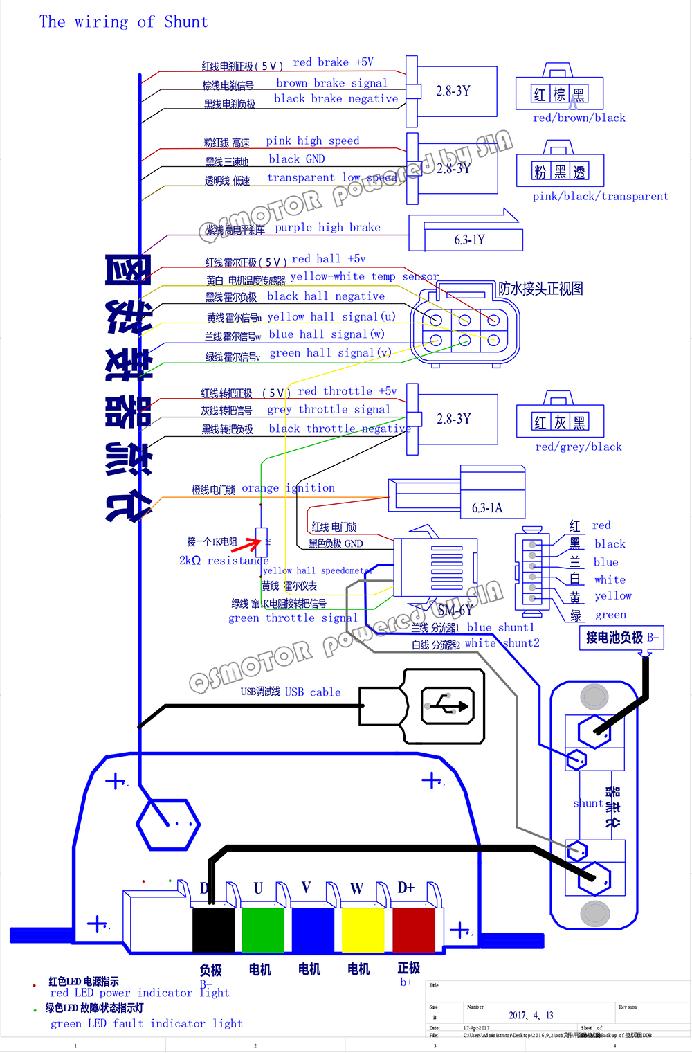
My controller doesn't have a CA-DP connector so I had to set it up to an external shunt. Ill attach an image below of the exact wiring diagram I followed in order to wire up my cycle analyst to my sabvoton controller. In the attached photo you will see a 2K Resistor on the throttle line, I do not have that connected although I have tried to put one in the past thinking it may solve my issue but it didn't work lol.
The wiring they show looks correct, as long as the Grey wire they indicate is indeed your throttle signal wire on the controller. (I've attached the linked image to this post in case it goes away at that linked site)
The resistor is not necessary, unless you *also* have a throttle directly connected to the controller at the same connector.
As long as there is a common ground (battery negative, etc) between the CA and the controller, then that plus just the throttle signal wire is enough to get the correct throttle signal to the controller. (as indicated in the diagram, the 5v doesn't get connected between the CA and controller, as each one is independently regulated).
So as long as the wiring is good between the CA and the controller, then it should be responding to the CA's throttle signal normally, exactly as if it were a direct throttle connection.
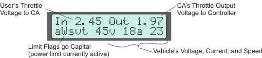
When I am on the main diagnostic screen this is what I see when my throttle is resting
In 0.85 Out 1.2
awsvt 76v 0A 0
and under full load the CA diagnostics screen reads
In 4.23 Out 4.39
awsvt 76V 0A 0
Those appear to be normal, except for the controller not drawing any current at full throttle.
")
The all-lowercase awsvt indicates that no limiting is occuring inside the CA, as any active limits would be capitalized. Similarly, if the CA were limiting, it would be reducing the throttle voltage output, which it isn't doing since the Out value is at your max throttle out value.
Also: It doesn't make any difference to the problem you're having (because you are getting throttle out as expected for the CA itself, at least up to the point the CA reads it's voltage internally), but I noted that your CA .hex file shows it is from the CA 3.1 beta 22 firmware, rather than the latest 3.14 version. Just to make sure, what firmware version does your CA tell you it is running when you first turn it on? (if it isn't 3.1b22, then perhaps the settings uploaded into the CA are corrupt even though it appears to be doing what it should, and that it might not actually be outputting what it says it is--I don't know if it is possible or not, but it is something to verify).
If it matters, there are various things fixed and/or upgraded between the old 3.1 version and the newer 3.14. I don't recall what they are, but the info is in the various release notes files inside the help folder for each different firmware version. If you want to you can use the setup program to upgrade the firmware on the CA to the latest, if you find that it would do something you want to do that the beta doesn't, or that it fixes a problem you are experiencing. I recommend that you write down the Protected settings values in the Calibration section on paper before upgrading, in case they are somehow lost. To see them you have to enable the "show protected settings" in the setup program Preferences menu.
Do you also have a digital aux setup connected to the CA? If not, you may want to disable the digiaux (set to "none") in the digital aux section. It isn't affecting your setup ATM, but various settings in the CA do interact and when a control isn't present that it thinks is connected, it may behave unexpectedly under some conditions.
Similarly, if you don't have a 3-speed switch (wired with resistors inside appropriately) connected to the aux in of the CA, you should also set that to "none".
Same for PAS--set that to "none" if you don't ahve a PAS cadence sensor hooked up.