
Roguenite
100 µW
- Joined
- Jun 26, 2020
- Messages
- 7
Hello everyone,
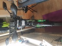
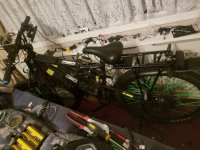
I have a 2 wheel drive bike.
2 x 1000W Voilamart motors
2 x 48V 13ah batteries (not parallel)
2 x Voilamart Sinewave controllers
2 x Greentime Squarewave controllers
I think some of you guys won't approve my build because I run 2 motors with 4 controllers.
But I have been riding to work everyday for over a year with this build with no issues. I use an ON/OFF/ON flick switch (3 speed switch on Aliexpress throttle) to change between the throttles of 2 sinewave controllers and 2 squarewave controllers. So only 1 controller's throttle is active for 1 motor at any time. However all 4 controllers are ON at the same time.
The reason I built it like this is because the regen braking I got by jumping pins in the Voilamart sinewavers is rubbish compared to the regen stopping power of greentime squarewave. But I prefer to drive with sinewave. (It was a cheaper way than getting the expensive controllers)
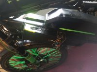
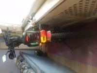
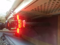
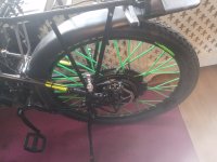
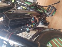
Everything had been working perfectly for over a year. After all the trials, fails and fixes were over, I finally decided to re-wire absolutely everything and make the bike look more clean.
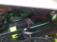
After the re-wiring, and during testing I noticed rear motor doesnt cutoff on brake pull and has no regen. The reason was low brake wire had 1V present. It was not shorting with ground or anything else. I found a PIN on the greentime controller labelled as 4.3V and jumped it to the low brake pin. That solved the no brake cutoff issue but still no regen.
I decided to just be happy with front motor regen as I'm too tired from rebuilding the bike already. But now front motor works only if both motors are active. (I had added an isolation switch for the 2 wheel ignitions in case I need to troubleshoot just one.) If i switch only front motor controllers, i hear the first click in the motor and but no response on throttle. Turns out after I joined the 4.3V pin to the rear wheel low brake, front controllers have gone to 0V and would only work using that 4.3V supply of rear controller. Hence rear ignition is off, front low brake is at 0V. (Low brake wires of all 4 controllers are joined together).
Now I gave 5V from throttle to low brake wire of front controllers and both wheels work fine on throttle and cuts off on low brake trigger. Except no-regen from either wheel.
I re-wired everything the same way as they were for the past year except I made the wires much shorter. Is it possible that I've blown the pull up resistors by making the wires too short? I read about pull up resistor on some threads here.
If anyone has some idea on what exactly is wrong with my low brake triggers and shed some light on how I can get my regen back I would really appreciate it.
Thanks
I have a 2 wheel drive bike.
2 x 1000W Voilamart motors
2 x 48V 13ah batteries (not parallel)
2 x Voilamart Sinewave controllers
2 x Greentime Squarewave controllers
I think some of you guys won't approve my build because I run 2 motors with 4 controllers.
But I have been riding to work everyday for over a year with this build with no issues. I use an ON/OFF/ON flick switch (3 speed switch on Aliexpress throttle) to change between the throttles of 2 sinewave controllers and 2 squarewave controllers. So only 1 controller's throttle is active for 1 motor at any time. However all 4 controllers are ON at the same time.
The reason I built it like this is because the regen braking I got by jumping pins in the Voilamart sinewavers is rubbish compared to the regen stopping power of greentime squarewave. But I prefer to drive with sinewave. (It was a cheaper way than getting the expensive controllers)
Everything had been working perfectly for over a year. After all the trials, fails and fixes were over, I finally decided to re-wire absolutely everything and make the bike look more clean.
After the re-wiring, and during testing I noticed rear motor doesnt cutoff on brake pull and has no regen. The reason was low brake wire had 1V present. It was not shorting with ground or anything else. I found a PIN on the greentime controller labelled as 4.3V and jumped it to the low brake pin. That solved the no brake cutoff issue but still no regen.
I decided to just be happy with front motor regen as I'm too tired from rebuilding the bike already. But now front motor works only if both motors are active. (I had added an isolation switch for the 2 wheel ignitions in case I need to troubleshoot just one.) If i switch only front motor controllers, i hear the first click in the motor and but no response on throttle. Turns out after I joined the 4.3V pin to the rear wheel low brake, front controllers have gone to 0V and would only work using that 4.3V supply of rear controller. Hence rear ignition is off, front low brake is at 0V. (Low brake wires of all 4 controllers are joined together).
Now I gave 5V from throttle to low brake wire of front controllers and both wheels work fine on throttle and cuts off on low brake trigger. Except no-regen from either wheel.
I re-wired everything the same way as they were for the past year except I made the wires much shorter. Is it possible that I've blown the pull up resistors by making the wires too short? I read about pull up resistor on some threads here.
If anyone has some idea on what exactly is wrong with my low brake triggers and shed some light on how I can get my regen back I would really appreciate it.
Thanks
Attachments
-
 20210405_133310.jpg285 KB · Views: 423
 -
 20210405_133550.jpg234.7 KB · Views: 423
 -
 20210405_133623.jpg233.5 KB · Views: 423
 -
 20210405_133253.jpg277.2 KB · Views: 423
 -
 20210405_133343.jpg273.6 KB · Views: 423
 -
 20210405_133354.jpg326.2 KB · Views: 423
 -
 20210402_204344.jpg338.8 KB · Views: 423
 -
 20210405_133315.jpg306.8 KB · Views: 423
 -
 20210405_133320.jpg277 KB · Views: 423
 -
 20210405_133549.jpg225.9 KB · Views: 423
 -
 20210405_133403.jpg310.8 KB · Views: 423
")

 )
)