BBSHD Wiring

Joined
Aug 29, 2019
Messages
53
Hi,

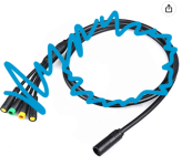
I'm trying to make one cable that has the Bafang 8 pin Higo connector on one end and display and throttle on the other (I don't need brake sensors in the wiring)

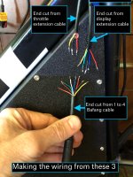
I've cut the 8 pin end from a 1 to 4 waterproof cable and trying to wire that into throttle and display extension cables.
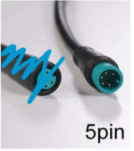
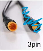
Before I chopped the 1 to 4 cable I tested each pin at the 8 pin end and noted which pin it related to at the 5 pin display and 3 pin throttle end.
I also confirmed which color wire went to which pin on the cut throttle and display cables (as they were different from the standard wiring in the Bafang diagram)

I've joined the relevant cables together and the C500 display does not work.
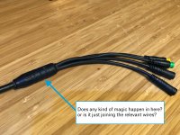
What I'm trying to understand is why it doesn't work if the same pins are connected, does the joining part on the 1 into 4 cable do something other than just going the right cables together?

Hope that makes sense!


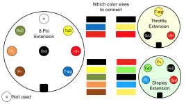
attached is the diagram I made to confirm where each pin ends up and it comes out the same as the Bafang wiring diagram.
(the blue scribbled out parts are what I've chopped off and what's left is what I'm using to make the wiring)
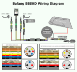
image_5494.png

Screen Shot 2022-06-02 at 2.11.50 PM.pngScreen Shot 2022-06-02 at 2.12.32 PM.pngScreen Shot 2022-06-02 at 2.12.37 PM.png
IMG_2745.jpeg
IMG_2746.jpeg
 
quelsurprise said:
I've joined the relevant cables together and the C500 display does not work.
By "does not work", do you mean it doesn't operate as expected, or it doesn't turn on, or displays unexpected data, or something else?


What I'm trying to understand is why it doesn't work if the same pins are connected, does the joining part on the 1 into 4 cable do something other than just going the right cables together?
AFAIK it is just a point at which all the cables come together, and is "potted" in plastic to waterproof the junction.
 
thanks,
when i press the power the screen looks like it starts to illuminate very faintly for a split second then goes dark again.
If i swap out the wiring for a 1 to 4 cable it illuminates and works ok.
I've gone over the pin positions and wires multiple times so a bit stumped as to why it won't power on.
 
Maybe there is a bad connection to the display ground or battery positive wire; it could be anywhere in the cable that doesn't work. It may even read correctly with an ohmmeter or continuity tester, but not under load. In that case it would show a voltage drop across the wire (meaning you would actually see a voltage difference between the controller end and the display end, where normally there would be no difference).
 
For your display connection, from controller to display, it should be BRN to RED, BLK to BLK, ORG to BLU, GRN to GRN, and YEL to YEL. How do you have yours connected?

Edit: I now see your connection diagram. Please try what I suggested. Your throttle connection looks good. Not sure if you already have it, but here, https://manuals.plus/m/55331b9f8d211bd3aa12a2bd292e27febf05a4f3cfc15aeea235e20d450bd98a_optim.pdf, is the manual for your display. On page 9, there is the wiring configuration that I used for reference.
 
Thanks Amberwolf, SlappHappyGamer!

amberwolf said:
Maybe there is a bad connection to the display ground or battery positive wire; it could be anywhere in the cable that doesn't work. It may even read correctly with an ohmmeter or continuity tester, but not under load. In that case it would show a voltage drop across the wire (meaning you would actually see a voltage difference between the controller end and the display end, where normally there would be no difference).

I'll test the voltage through the P+ and Ground pins at both ends.

slaphappygamer said:
For your display connection, from controller to display, it should be BRN to RED, BLK to BLK, ORG to BLU, GRN to GRN, and YEL to YEL. How do you have yours connected?

Edit: I now see your connection diagram. Please try what I suggested. Your throttle connection looks good. Not sure if you already have it, but here, https://manuals.plus/m/55331b9f8d211bd3aa12a2bd292e27febf05a4f3cfc15aeea235e20d450bd98a_optim.pdf, is the manual for your display. On page 9, there is the wiring configuration that I used for reference.

thanks for digging out the display manual, for my set up I've been ignoring the colors on the throttle and display extension cables as they seem to be different from Bafang standards. Instead I traced where each pin from the stock 1 to 4 cable ended up and replicated that in the wiring I'm making.
I just attached a new diagram with how I have it wired based on the Bafang wiring diagram names

Removed diagram image to avoid more confusion :)
 
I just re-checked which pin corresponds to which color wire on all cables, on the display and throttle extension leads I'd marked them down incorrectly, the attached diagram now has the correct colors to pin positions.

I hooked up the wiring using these wires/positions and the display now comes on for a second then goes off, if I hold the power it stays on a bit longer then goes off.

But! now if I hook the display up to an unmodified 1 into 4 cable it behaves the same and won't stay on :(
Could this have damaged the controller or display?

Removed wiring diagram
 
Hi quelsurprise,
And HEY,welcome to the forum! :)

Was following along nicely, and agreeing with your logic till the pin-out position locations mentioned here...

quelsurprise said:
Just tested the voltage on the display connecter, on the P+ and Ground pins (positions 3 and 5) and it shows the same voltage as the battery

If you've changed the pin designations from the original wiring diagram, that's fine. But you may want to update your new wiring diagram pin designations to reflect what your going with.

I find the most difficulty with these connections is when a male or female pin-out is shown and you accidently miss mirroring the opposite side.

That is why I am glad that you took a voltage reading on the display connector. With both battery voltage, 5vdc regulated voltage and communication wiring involved, no guess work is acceptable. :shock:

That said, I'm wondering if a P+ to PL display pin voltage check would also be similar. (between the two, the larger voltage difference would have the true ground wire on the negative side...) You could check that, as well as checking resistance from battery negative connection to the display ground pin to eliminate all doubts. (battery disconnected.) And for good measure compare those voltages with those at the main 8 pin connector off the motor where mirroring on these pins may be less confusing...? (True ground in the middle!)

Have you tried starting the display with the throttle disconnected?

From what I understand...

Bafang Operational Sequence.

With battery connected, full battery power is available at display P+ pin to ground. 5vdc regulated controller power is NOT available at the throttle 5vdc pin at this time
When display "On" button is pressed for two seconds, power is provided to the display energizing it's 5vdc supply. As well as sent down the PL display wire to provide power for controller 5vdc regulated power. (AKA key lock) Thus powering up the communications and controller operating electronics. Now 5vdc should be available between the throttle 5vdc pin and throttle ground.

With these steps in mind you can see how important it is to identify the correct P+,PL, and ground pins to start with. Then move on to get the controller energized.

This also explains why you can jumper the display connection, to test to see if you have a bad display, as seen in section 2.2...
https://electricbike.com/forum/foru...s/bbshd/39217-troubleshooting-the-bbshd-bbs02

Screen shot from link above...


fetch


Anyway, it looks like the 8 pin white wire goes unused and taped off. With 2 wires, (throttle RED, and display BLUE) connecting to 8 pin BLACK.


Respectfully submitted,
T.C.

Rats, see I am a little too late... :(
 
Hey Tommy!

thanks so much for the info, I'm going to step away from this for a bit and come back with a fresh mind tomorrow and use your approach, hopefully something will click and i'll figure what's up.
At this point i have less of a clue than i did at the start!

One other thing i did notice was if i hold the power on the display it does stay on until i let go, and it shows the battery voltage as 7.7v,
i'm pretty sure once i read through and comprehend the details you send i'll understand why.

appreciate your help

tempImagewHDSh0.gif
 
Glad you got this working. Trouble isolation can get tiresome real fast.

Now that I see your display, I realize that I shared the wrong manual with you. That manual was for the c500. You actually have a 500c. Pretty easy to mix those up.

Here is your manual
https://cdn.shopify.com/s/files/1/0537/7176/3911/files/500C_Display_Manual.pdf?v=1619714642

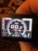
The 30H error code is stated as a communication fault. You probably just need to reverse the TX and RX. Not sure about the voltage. Seems like your have throttle voltage activating your display.
 
Hi!

so I think the controller maybe frazzled?

I've triple checked the pin to color positions on the cables I'm trying to join, the cut off 8 pin extension to be joined to the cut off display and throttle extension harness ends.

I'll delete all previous diagrams and this new attached one I think should be correct, if you do have a minute can you please confirm the functions are labelled on the correct pins.

Back to the controller, I bridged the PL and P+ pins straight on the motor harness and the throttle doesn't work, I also have a programming cable which I plugged into to the display connection (on a new 1 to 4 cable) and the same result, the throttle doesn't work.

Testing the voltages across the pins, both fluctuated a little bit the settled,
P+ to PL = 34
P+ to Ground = 36

double checked the voltage at the battery directly and it's as expected, around 56v
 
The pin-out locations look good. And with the wire colors corrected and your current voltage checks, (although not quite right) I think you have the wiring straightened out.
With the colors mirrored previously, that would have full battery voltage, with a complete short to ground going thru your display when powered on. :(

Checking at just the 8-pin female motor connector. With everything else disconnected, After carefully jumping P+ and PL, I would directly check for 5vdc just to be sure the throttle or possible damaged harness cables aren't causing problems. NOTE: Remember to mirror pin-outs from male side! Check for battery voltage again on the correct pin holes first. Then for 5vdc...

Or using tips from this thread...
https://electricbike.com/forum/foru...r-throttle-operation-testing-and-modification
You may want to check your throttle directly.
 
Thanks for confirming the pin outs and help!

Just tested straight on the motor/controller harness (making sure to mirror the positions, thanks!)
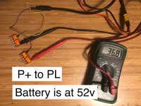
Volt meter across PL and P+ reads 36.8v, tested the battery directly again and it's at 52v

Jumped PL and P+ then measured across Ground and +5v and it shows no voltage.

I'll read up on the throttle testing and give that a go, though I'm assuming the low voltage from the controller means something is is not right there?

IMG_2762.jpeg
IMG_2763.jpeg
 
Job well done on all the testing. Unfortunately, it looks as though the controller is bad.

When you test your battery power directly, is it with P+ and PL jumped with the battery connected?
Is there any current draw at that time?

As far as the display. I'd be very wary of re-using it. I would probably open it up, and check for any toasted electronics on the PCB.
And perhaps bench test it (with some fuse protection)to see if it lights up and holds full battery power to PL when the "on" button is released. Just using P+, PL, and ground. You could switch these tests around if desired...
 
Hi Tommy

For testing the battery I'd just put the volt meter on the battery XT60 without the controller attached, which showed 52v.

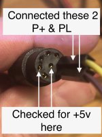
Then when testing the controller female 8 pin connection I had the battery connected to the controller and put the voltmeter on pins 1 and 2 (reversed as it's the female side, so the 6th and 7th positions as in the photo)
That showed 36.8v

Then for the last test I bridged the same 6th and 7th positions and put the voltmeter on positions 2 and 8, again, as positions as you look at the female connector.

I've ordered a controller and display, and thanks for the warning and testing steps on the display, I won't plug it in to anything unless I can be 100% sure it's ok!
 
And we're back in business!

I think the main confusion I had was whether the existing Bafang wiring diagrams were showing the motor connector, speed and display connections or if it was the 4 to 1 cable in between them, I noticed that the Luna wiring diagram has a photo of the actual connection on, wish I'd found that one first.

Lessons learned,
- if making a wiring loom from different cables always confirm which colors go to which pins, the speedo and display extension cables I had did not use the same colors as the 4 to 1 cable.
- if testing directly on the controller, display or speedo wiring remember to flip the layout horizontally
- making a diagram was very helpful to refer to

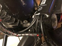
Speedo and Display cables are now running in the frame :D
thanks all for the help getting me through it!

IMG_2961.jpeg
IMG_2973.jpeg
 
Back
Top