TwisterGripper
10 mW
- Joined
- Aug 1, 2017
- Messages
- 21
Hi all, this is my first time replacing a bms so learning as i go.
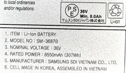
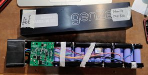
I picked up a Genze 101, it has a samsung sdi battery pack, which the bms mysteriously died over the winter...tried the wake up trick, everything. pack is charged, but no output...pretty sure the BMS is just dead.
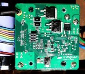
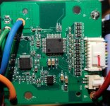
BMS is "Alton 10s Rev: X001 '2013.07.29" which i cannot find the original anywhere, nor datasheets or anything. so looks like i have to install a different bms.
Problem is, the sensor wire harness is 9 wires (its a 10s pack), and a separate 2 pin connector for the temp sensor.
All I can find for replacements have 10 or 11 pins on the harness. that makes me very nervous and unsure how to go about repairing it.
Looking at this BMS- could this be suitable? https://www.amazon.ca/dp/B075MDQ92X
I just dont know what to do about the extra wires on the harness....
Looking for suggestions &/or any guidance is appreciated...or link to a suitable BMS
Attached pics of bms/pack.
I picked up a Genze 101, it has a samsung sdi battery pack, which the bms mysteriously died over the winter...tried the wake up trick, everything. pack is charged, but no output...pretty sure the BMS is just dead.
BMS is "Alton 10s Rev: X001 '2013.07.29" which i cannot find the original anywhere, nor datasheets or anything. so looks like i have to install a different bms.
Problem is, the sensor wire harness is 9 wires (its a 10s pack), and a separate 2 pin connector for the temp sensor.
All I can find for replacements have 10 or 11 pins on the harness. that makes me very nervous and unsure how to go about repairing it.
Looking at this BMS- could this be suitable? https://www.amazon.ca/dp/B075MDQ92X
I just dont know what to do about the extra wires on the harness....
Looking for suggestions &/or any guidance is appreciated...or link to a suitable BMS
Attached pics of bms/pack.