Custom Bike Electrical Issues

Ryzen

1 mW
Joined
Oct 1, 2022
Messages
14
I think I might have fried one of my motor controllers when I plugged my battery into it (the 48-72V 1500w one). I am aware in the image the power + and - are backward but I connected them correctly. There was a big spark when I touched the positive leads and it never made my motor turn when using the throttle with all of my wires connected correctly. I have a new controller and was looking for advice to ensure I don’t fry a second one (VEVOR). Safety of my setup aside is there anything I am missing or a way to prevent welding my fuses to my wires when I connect them? I attached images of my setup. Big thank you to anyone who tries to help in advance! :)
 

Attachments

  • Battery.jpeg
    Battery.jpeg
    417.6 KB · Views: 1,827
  • Motor Controllers.jpeg
    Motor Controllers.jpeg
    318.6 KB · Views: 1,827
  • 2C1B58C6-37F6-4330-BBBB-CF03451821C2.jpeg
    2C1B58C6-37F6-4330-BBBB-CF03451821C2.jpeg
    459.7 KB · Views: 1,827
  • 55F08244-B9A9-4864-8C6A-8FBA72283A2F.jpeg
    55F08244-B9A9-4864-8C6A-8FBA72283A2F.jpeg
    217.3 KB · Views: 1,827
No, it hasn't worked before. I have ruled out it being the throttle though. Nothing has changed since my initial attempt to get it to spin. Thank you for your super fast response I really appreciate it!
 
So a couple of things, not sure what your background is, so I will be somewhat detailed.
First off, I see the controller you plugged in is rated for 72 volts, and it looks like your battery is resting at 81 volts, without knowing how much voltage headroom you have on that controller, or the programmed over voltage shutoff, that could be a first cause.

Second off, any controller is going to have what are called DC link bus capacitors, in general, a capacitor is like an extremely low resistance short depending on the voltage differential of the capacitor and the incoming battery voltage, this can cause a gigantic amperage surge, which can do all kinds of nasty things to the MCU, DC-DC power supply, etc.

One thing I have also heard is you want to connect the negative lead to the controller first and then connect the positive lead second, that way ground reference of the MCU and other sensitive electronics does not bounce or go below ground( -0.3 volts below ground is enough to fry most silicon based ic's).

Solutions to the inrush current take many forms,

In the most basic form, you want to limit the current that is rushing in to fill the capacitors, a fairly easy way is to hook up the negative lead, then connect the positive lead to the controller through a few hundred ohm power resistor, this limits the amount of current that can rush in while the capacitors are filling up from the battery, this usually takes a second or two depending upon the size of the capacitors, and the value of resistor you have chosen.
Once the capacitors are full you bypass the resistor with a connector / wire that is the same size as your battery and controller wires, because the resistor will not be able to move the amount of current needed to actually operate the motor. This is sometimes called a loop key.

I prefer a loop key for its simplicity, repair-ability, DIY, etc.

https://duckduckgo.com/?q=loopkey+resistor&atb=v300-7__&iax=images&ia=images
 
That's extremely helpful and informative! I opened the controller and the capacitors are labeled 80V. I had assumed that the manufacturer would have accounted for the max capacity of a lion nominal voltage 72v is 84v and adjusted accordingly. So thank you for bringing that up.
You mentioned resistors, I had actually thought of this ahead of time and bought these resistors https://www.amazon.com/dp/B0185FHG76?ref=ppx_yo2ov_dt_b_product_details&th=1from amazon.
I have them on my negative side of the battery and when I touch them to the controller they catch fire immediately.

Would you suggest removing 2 of my batteries to keep them under 80v?
Do the resistors need to be on the positive side?
Would you recommend any certain resistor orientation for the initial charge?
Lastly, would you think these resistors are even strong enough?

Sorry if that is laid out kind of socially I'm not too used to posting on forums. I really appreciate your help with this!
 
A-DamW said:
So a couple of things, not sure what your background is, so I will be somewhat detailed.
First off, I see the controller you plugged in is rated for 72 volts, and it looks like your battery is resting at 81 volts, without knowing how much voltage headroom you have on that controller, or the programmed over voltage shutoff, that could be a first cause.

A "72v" system is only nominally that. It's going to expect a "full" voltage of about 84v, for a 20s x 4.2v Lithium battery; any controller rated for 72v will be able to handle at least that, and is likely to have 100V+ parts inside for anything on that bus.


The resistor-during-intial=battery-connection is typically called Precharge; there's a bunch of threads with variations on this, including switches and connectors with built-in precharge resistors, or building a connector system that engages the precharge first and then the mains (either automatically or manually).

While the initial surge could cause controller damage, it much more commonly causes problems with batteries (BMS shutdown from overcurrent, or blown fuses, plasma-damaged connectors, etc.
 
Ryzen said:
Would you suggest removing 2 of my batteries to keep them under 80v?
No, your controller, if actually built correctly as a 72v controller (which it should be, but some sellers lie), can handle 84V just fine.

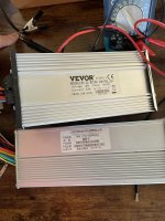
However: The Vevor controller is marked as a 48v controller, and could have (probably does) have parts that can't handle higher than say, 60-63V. So I wouldn't put any bets on it working with a 72v pack.

See this post about considerations on what parts in a controller need to handle battery voltage:
https://endless-sphere.com/forums/viewtopic.php?f=35&t=117411&p=1734433#p1733690


Do the resistors need to be on the positive side?
Doesn't actually matter--they limit inrush current, and so can be anywhere in the loop from battery to controller.

However, they need to be able to handle the total power dissipation (watts) created during precharge. Ohm's law and Watt's law will help you calculate what you need.

Let's say you have a 200ohm resistor. At connection, it has 84v across it. 84v / 200ohms = 0.42A. 84v x 0.42A = 35.28W. So for that initial burst, you'd need a resistor capable of dissipating at least 35W of heat. LIke these 50w resistors:
https://www.amazon.com/LM-YN-Wirewound-Electronic-Industrial/dp/B076W87ZT8
81ciWhg-gmL._AC_SX425_[1].jpg

The current (and power) will drop at the rate the capacitors charge. The time this takes depends on how much capacitance there is, vs how much current is flowing. Big controllers have a lot of capacitance.
http://www.learningaboutelectronics.com/Articles/How-long-does-it-take-to-charge-a-capacitor
Call it 5 times the T=RC to essentially fully charge them, where T is in seconds, and R is the precharge Ohms, and C is the uF of the caps. 1x that to get 63% of the way there.

Let's assume you have 10,000uF of caps in there (there's probably only 2000, cuz everybody's cheap, but for worst-case math....). 200ohms x 10000uF (which is 10mF, or 0.01F) = 2s (200 x 0.01). So after 2 seconds, the current will have dropped dramatically, and heat will be way less. After 10 seconds, they'll be pretty much fully charged. (realistically, you only need the precharge for the first portion of time, 2s in this case).

If you only have 2000uF of capacitors in there, it'll take 1/5 of that time.

That means you might get away with a much smaller resistor, like say 10W...it'll get really hot during inital inrush, but not much heat will be generated after that so it might be able to dissipate that heat, if it's in open air.

If it's enclosed where there is no airflow, you should probably stick to a resistor with a much higher wattage rating, higher than you need, to be sure it doesn't overheat. Keep in mind also that it will be shedding that heat into whatever is next to it, surrounding it, so don't put it somewhere it will melt or damage things--even though the intense heat is only there for a few seconds, if there's enough energy over enough time in a confined enough space, it can melt or damage stuff if it's sensitive to such temperatures. It really depends on how much total heat there is, and how long it is there for.

A higher ohms resistor will create less heat (current is lower, so watts are less), but it will take longer to precharge.
 
Ryzen said:
There was a big spark when I touched the positive leads and it never made my motor turn when using the throttle with all of my wires connected correctly.
Can you post a diagram of exactly how you have everything connected? Not the diagram they provide, but a drawing of exactly how *you* wired it, traced out from your actual wiring.

This will help us help you ensure every wire you need is connected, and is where it needs to go.

It will also be useful to you for later troubleshooting, modification, upgrades, etc., when you've long forgotten what went where and why. ;)

The most common issue with a new setup not responding to input is not connecting the KSI (keyswitch / ignition) wire to battery positive. It may be called other things by the seller or manufacturer; it is usually a thin red or orange wire bundled with the main battery + and - wires. Sometimes it is a separate loop of wire with connectors on it to be plugged into itself or into a switch, sometimes it is a single bare-ended wire.

Because it's being connected to battery voltage, you don't want to connect the wrong one--almost all the thin wires on the controller are 5V-level signals (or grounds) and connect internally to things that would be destroyed by battery voltage.


Safety of my setup aside is there anything I am missing or a way to prevent welding my fuses to my wires when I connect them?
I'm not sure what you mean by the bolded part.

Exactly how are you connecting the fuses, and to which specific wires? A picture showing this, or drawing, is the best way so we can see what might be wrong to help you correct it.
 
Regarding your battery, some potentially important notes (in case you don't already know this stuff) and questions to try to make sure this battery will safely do what you want:

Any battery built of recycled cells should use only the same brand and model of cell, and have them all tested and matched to each other as closely as possible in all characteristics, in order to perform best for longest.

Any battery built of mismatched types of cells (like yours) can't really have this done; the best you can do is get as many cells as possible, then test all the cells for capacity and internal resistance, etc., and then use only the ones that are closest in all characteristics.

Any groups that are different as a whole from other groups in series with them, will behave differently from those groups under load or during charging.

Cells for some uses can't handle high currents, but may have higher capacity. Other cells may have lower capacity but be able to handle higher currents. Putting the low-current (low-C-rate) cells under higher loads stresses them and causes more internal heating than they're meant for, and causes greater voltage sag, which loses you power (watts) available to your system because it's wasted as heat inside the cells instead.

Because you can't really know the history of any recycled cells, you can't predict their future behavior, either. So it's best to keep an eye on their behavior, either manually with periodic testing, or with a BMS that lets you monitor each group during usage / charging / etc (if it logs conditions, even better), so you know when any of them begins to misbehave.


Build notes: Some of the cells look like they have no shrinkwrap, and no insulator on the positive end between the cell can and the interconnect strips. It's possible in this case for sufficient pressure on the strips at that point to push them onto the can, which will directly short across the entire parallel group. (at best, that will kill those cells, at worst it will generate enough heat to cause a fire).


So, some questions, to help make sure your pack will do what you want for as long as you need it to:

What were the sources for the cells?

Have all the cells been tested and characterized, and then matched before building into the pack?

Do you happen to know the various cell brands and models used in this pack, and their characteristics?

Are you using (or going to use) a BMS? If so, which one?

How much current does this pack need to supply, peak and continuous?

Some supposition, with notes and cautions:

It looks like a 20s4p pack. The controllers say 33A for the Vevor, and 45A for the other one. That is *probably* a continuous rating, and peak could be up to double that for a few seconds or less, if the load is high enough (like startup from a stop), depending on how they designed the controller. So...45A / 4p would mean a little over 11A per cell. That's high for some cells even when new...recycled cells might not handle that at all well.

Might be ok if you don't need that current for very long (seconds at a time), but if the cells can't handle it and it has to draw that kind of current for minutes at a time, it could damage cells if there's no BMS to shut the system off if voltage drops too far on the individual cell groups, and the voltage drops and stays below the safe lowest voltage limit of the particular cells long enough to cause problems with them.
 
If I have a controller that's rated 45a 72v would it be safe to 1) Connect my battery below attached to it without a BMS? If not would it be ok to use a 100a Bms or what kind of BMS should I use if this would not be a good configuration? I am very new to this side of things and couldn't find an answer anywhere, so sorry if this is a common question. I appreciate any answer in advance! :)
 

Attachments

  • unnamed (1).jpg
    unnamed (1).jpg
    1.5 MB · Views: 289
999zip999 said:
Is that 20s5p ? I'm guessing ? Tell me about the cells. Do you have a !ink for the controller ?

Yes, it is 20s 5p. The batteries are all old mixed and matched 18650 laptop batteries from a recycling center. I tested them with a volt meter upon purchase and put any cells below 2v aside. I used the Liitokala lii-500 full cycle on every battery and used a thermal camera to make sure the temperature never rose above factory specs. Using the information provided my the LiitoKala I welded them into groups all very close to ~10ah total. I used a homemade welder from an old microwave transformer to weld the nickel strip to the batteries. The admittedly bad soldering job was also done by me, it is 8AWG wire. If there is anything more I can do ill try to respond as fast as possible! Thank you for the help!

This is a link for the controller from a different seller: https://www.ebay.com/itm/3743433427...DWrJdirwZHyisnB3LFwXAZyfniE=|tkp:BFBMgJmmkYth

My seller was discountranilaptop: https://www.ebay.com/str/discountranilaptop

This is the LiitoKala Li-500 link: https://www.amazon.com/LiitoKala-Lii-500-Battery-charger-capacity/dp/B073R7VCMZ
 
amberwolf said:
Regarding your battery, some potentially important notes (in case you don't already know this stuff) and questions to try to make sure this battery will safely do what you want:

Any battery built of recycled cells should use only the same brand and model of cell, and have them all tested and matched to each other as closely as possible in all characteristics, in order to perform best for longest.

Any battery built of mismatched types of cells (like yours) can't really have this done; the best you can do is get as many cells as possible, then test all the cells for capacity and internal resistance, etc., and then use only the ones that are closest in all characteristics.

Any groups that are different as a whole from other groups in series with them, will behave differently from those groups under load or during charging.

Cells for some uses can't handle high currents, but may have higher capacity. Other cells may have lower capacity but be able to handle higher currents. Putting the low-current (low-C-rate) cells under higher loads stresses them and causes more internal heating than they're meant for, and causes greater voltage sag, which loses you power (watts) available to your system because it's wasted as heat inside the cells instead.

Because you can't really know the history of any recycled cells, you can't predict their future behavior, either. So it's best to keep an eye on their behavior, either manually with periodic testing, or with a BMS that lets you monitor each group during usage / charging / etc (if it logs conditions, even better), so you know when any of them begins to misbehave.


Build notes: Some of the cells look like they have no shrinkwrap, and no insulator on the positive end between the cell can and the interconnect strips. It's possible in this case for sufficient pressure on the strips at that point to push them onto the can, which will directly short across the entire parallel group. (at best, that will kill those cells, at worst it will generate enough heat to cause a fire).


So, some questions, to help make sure your pack will do what you want for as long as you need it to:

What were the sources for the cells?

Have all the cells been tested and characterized, and then matched before building into the pack?

Do you happen to know the various cell brands and models used in this pack, and their characteristics?

Are you using (or going to use) a BMS? If so, which one?

How much current does this pack need to supply, peak and continuous?

Some supposition, with notes and cautions:

It looks like a 20s4p pack. The controllers say 33A for the Vevor, and 45A for the other one. That is *probably* a continuous rating, and peak could be up to double that for a few seconds or less, if the load is high enough (like startup from a stop), depending on how they designed the controller. So...45A / 4p would mean a little over 11A per cell. That's high for some cells even when new...recycled cells might not handle that at all well.

Might be ok if you don't need that current for very long (seconds at a time), but if the cells can't handle it and it has to draw that kind of current for minutes at a time, it could damage cells if there's no BMS to shut the system off if voltage drops too far on the individual cell groups, and the voltage drops and stays below the safe lowest voltage limit of the particular cells long enough to cause problems with them.

I'm sorry for the long wait time between my responses, life happened and I had to put my interest on hold. As for your questions, my answers are as follows.

You mentioned "Build notes: Some of the cells look like they have no shrinkwrap, and no insulator on the positive end between the cell can and the interconnect strips. It's possible in this case for sufficient pressure on the strips at that point to push them onto the can, which will directly short across the entire parallel group. (at best, that will kill those cells, at worst it will generate enough heat to cause a fire)."

Before I take anything off the test bench I plan to do just that, rewrap all damaged shrink wrap, redo all of my welds, and add insulating rings. All for practical use and safety. It has been left alone as the battery will not be moving in any way until I have a somewhat functioning system while keeping the experimental cost down. Then it will be properly shrink-wrapped with a BMS, proper welds, and insulating rings.

1. What were the sources for the cells?
They are all recycled drill/laptop batteries.

2. Have all the cells been tested and characterized, and then matched before building into the pack?
I have tested all of the cells using a LitoKalla Li-500, using the full cycle to find the ah capacity and using that to make all my parallel groups ~10ah. During this process, I also recorded every batch with a thermal camera to make sure none of them had high internal resistance, if they did I put them aside. Any batteries with a voltage lower than 2v when I got them were also set aside.

3. Do you happen to know the various cell brands and models used in this pack, and their characteristics?
3 kinds of Panasonic (lots of Panasonic NCR3500 specifically), Sayano, JGNE, and a few miscellaneous ones that are dark purple or grey in color as well as a few red ones that aren't from Sayano. I can't find a brand for those last 3 on the cell or in the online 18650 tables.

4. Are you using (or going to use) a BMS? If so, which one?
I was hoping to produce a spin of ANY kind, for a few seconds at the most, before investing in a BMS. If I was to buy one though it would be this one 20s 80A. Unless there is a better recomendationhttps://www.aliexpress.us/item/3256...00028850998512!sea&curPageLogUid=1NabIxzk7Vt8

5. How much current does this pack need to supply, peak and continuous?
I don't know how to calculate the peak, that is one of my concerns when I first connected to my controller, worried I fried the controller with the peak current. However continuous my goal is =<60a. Before I attempt that though as you pointed out the current draw is too high at the moment. If I can get my motor to spin at all, even with a little throttle, I plan to double the current parallel size bringing it to 20s 10p. That would mean a continuous draw of 6A from each battery. If I need to increase my parallel connections by more than 10 to lessen the draw from an individual battery I can do so. I have ~300 useful cells left.

Sorry again for the delay, if you happen to respond, ill do my best to get back to you as soon as possible!
 
docw009 said:
I see the voltmeter hooked up with red lead on what should be the positive lead of the battery, and yet it shows -81 volts. I want to see a picture of how that red battery lead comes off those cells.

Sorry again for the long response time, here is a more top-down view of my battery if that helps you at all! If you respond ill get back to you within a few hours this time!
 

Attachments

  • unnamed.jpg
    unnamed.jpg
    1.3 MB · Views: 250
Thank you for the full photo of your battery. Then you agree that the red lead on the right side is positive 80 volts, and the black lead is ground. And that was how you connected the first controller. That picture of the meter reading -81 volts does puzzle me.

At this point you are not using a BMS and you want to know if that is OK? The problem with no BMS is there is nothing to keep the 80 volts your measured evenly distributed across the 20 series groups. You should check them to see how they look, all 20 groups. With unmatched cells, they can charge unevenly. You do not want a condition where any cell group goes above 4.20 volts as that can damage those cells. If no cell group exceeds that max value, it's OK to use the battery to test the setup. but you're better off getting a working BMS on it.
 
docw009 said:
Thank you for the full photo of your battery. Then you agree that the red lead on the right side is positive 80 volts, and the black lead is ground. And that was how you connected the first controller. That picture of the meter reading -81 volts does puzzle me.

At this point, you are not using a BMS and you want to know if that is OK? The problem with no BMS is there is nothing to keep the 80 volts your measured evenly distributed across the 20 series groups. You should check them to see how they look, all 20 groups. With unmatched cells, they can charge unevenly. You do not want a condition where any cell group goes above 4.20 volts as that can damage those cells. If no cell group exceeds that max value, it's OK to use the battery to test the setup. but you're better off getting a working BMS on it.

My guess for the -81 it's the black and red lead holes on the voltmeter are switched, reversing the reading. As for the overcharging concern, I don't plan to charge this battery in any way without a BMS, if I can get any sign of my setup working I plan to use this BMS https://www.aliexpress.us/item/3256...00028850998512!sea&curPageLogUid=1NabIxzk7Vt8
 
My concern is battery does not have enough cells in parallel to support 45amp for a long life. Brand new Panasonic b cells only produce 10a brand new or would need 7p for 45amp and long life.
Plus you may not have the right color combo for the hall sensors and phase wires as the colors rarely match.
The resistor is to small for a prersistor.
What part of the country you from ?
 
E-HP said:
Ryzen said:
There was a big spark when I touched the positive leads and it never made my motor turn when using the throttle with all of my wires connected correctly.
How do you know this?
Ryzen said:

What happened when you ran the self learning routine?

I know the wires were connected correctly because I matched the colors according the the attached diagram with the controller. I marked on each image the wires I was connecting. I tried both of the possible 3 wire throttle lines just to make sure that wasn't an issue as the translations are a bit rough. (attached images)

As for the self learning routine, I was not familiar with this function, neither my throttle's or motor had a wire to connect it, as well as no guide I found online had a mention of it.
 

Attachments

  • Inkeds-l1600 (1).jpg
    Inkeds-l1600 (1).jpg
    214.4 KB · Views: 193
  • Inkeds-l1600 (2).jpg
    Inkeds-l1600 (2).jpg
    213.5 KB · Views: 193
999zip999 said:
My concern is battery does not have enough cells in parallel to support 45amp for a long life. Brand new Panasonic b cells only produce 10a brand new or would need 7p for 45amp and long life.
Plus you may not have the right color combo for the hall sensors and phase wires as the colors rarely match.
The resistor is to small for a prersistor.
What part of the country you from ?

I am from Ohio and I had the exact thought about the colors not matching up for the hall sensors. However the motor controller supports a no-hall motor, the wording is a little rough but the same product from other sellers say the same thing, that it supports a no-hall motor (attached). When I was making my connections I made sure the hall sensor wire colors in my controller plug matched the hall wire colors from the motor. Just to make sure, I did a double-check to make sure they were even lined up to the same color from both sides of the connection. Of course, I also made sure the phase wires were the same color when connecting.

As for the long-life concern, I plan to make the parallel connection 10p+ once I can create some kind of movement for a few seconds. I only plan to run the current setup to get a spin, then double the battery size once I know the components work in theory. Thank you for making sure I won't ruin my batteries I appreciate the caution!
 

Attachments

  • Screenshot 2022-11-09 144642.png
    Screenshot 2022-11-09 144642.png
    345.7 KB · Views: 193
Ryzen said:
E-HP said:
Ryzen said:
There was a big spark when I touched the positive leads and it never made my motor turn when using the throttle with all of my wires connected correctly.
How do you know this?
Ryzen said:

What happened when you ran the self learning routine?

I know the wires were connected correctly because I matched the colors according the the attached diagram with the controller. I marked on each image the wires I was connecting. I tried both of the possible 3 wire throttle lines just to make sure that wasn't an issue as the translations are a bit rough. (attached images)

As for the self learning routine, I was not familiar with this function, neither my throttle's or motor had a wire to connect it, as well as no guide I found online had a mention of it.
Matching color is not a reliable way of making sure things are wired correctly, unless, sometimes, you bought all components in a kit.

Nothing it going to work if you don't run the self learning routine by connecting the white self learning wires (with the wheel off the ground), and letting the self-learning do it's thing; then unplug when done. The throttle should work after that.

If you are running sensorless, you need to unplug the hall wire connector.
 
amberwolf said:
Ryzen said:
There was a big spark when I touched the positive leads and it never made my motor turn when using the throttle with all of my wires connected correctly.
Can you post a diagram of exactly how you have everything connected? Not the diagram they provide, but a drawing of exactly how *you* wired it, traced out from your actual wiring.

This will help us help you ensure every wire you need is connected, and is where it needs to go.

It will also be useful to you for later troubleshooting, modification, upgrades, etc., when you've long forgotten what went where and why. ;)

The most common issue with a new setup not responding to input is not connecting the KSI (keyswitch / ignition) wire to battery positive. It may be called other things by the seller or manufacturer; it is usually a thin red or orange wire bundled with the main battery + and - wires. Sometimes it is a separate loop of wire with connectors on it to be plugged into itself or into a switch, sometimes it is a single bare-ended wire.

This was an amazing idea sorry I missed it when re-reading the forum. I had temporally borrowed the motor from a friend, would it be a good idea to buy this kit from amazon and return it if I get the motor to spin and if I break it to just accept the loss, or would I immediately ruin the controller/motor if I attempted the connection to my battery? https://www.amazon.com/RibasuBB-Ele...g-goods&sprefix=72v+,sporting,103&sr=1-7&th=1
 
Just like my girlfriends Alfa Romeo 85 sprider from factory. That car stop me working on cars.

I
would put a precharge resistor on POS. side and plug in before main POS. A controller can take a hard start till the caps blow up 72v.
 
Back
Top