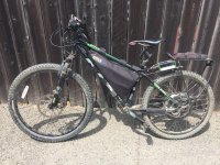
5kW Custom Hard-Tail Commuter

drdrs

1 W
Joined
Jun 10, 2018
Messages
50
This is a bike that has been under evolution for about 2 years now. It started as a KHS Alite from Luna Cycles with a Hailong pack and a BBS02. Now it has

- Crystalyte 3540 rear hub motor
- ASI BAC 2000 (green and black) controller
- Custom 14s5p HG2 battery with Energus Tiny BMS
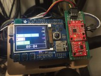
- Custom Arduino/TFT display with digital connections to BMS and ASI and datalogging
- Custom wiring harnesses for the controller and handlebars
- Variable regen left hand throttle

A couple of specs and measurements

- Peak observed electrical power 5.59 kW
- Best 0--30 mph GPS app time 5.3 seconds
- Top speed around 40 mph
- 29.3 kilograms

I'll post details in the future about the display and the battery.
IMG_2117.JPG

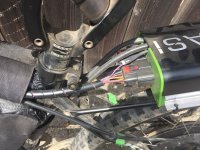
I've crimped a connectors for the throttle and braking inputs to the controller as well as the hall and motor temperature inputs.
IMG_2118.JPG

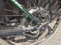
Crystalyte motor and Grin torque arm.
IMG_2119.JPG

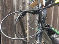
I tried to clean up the handlebars by using the Hirose DF62 connectors for the throttle, regen, and kill switch. The display is still a rats nest since it is under development. Hydraulics will be trimmed soon.
IMG_2120.JPG
 
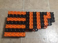
The battery for the bike uses 14s5p LG HG2 cells with the Vruzend battery caps and the Energus Tiny BMS 150 amp BMS. The top current I've observed so far is about 120 amps so the electrical power output is just above 5.5 kW.

Since this was my first battery, I laid it out in a very simple configuration to reduce the probability of wiring errors.


IMG_2075.JPG


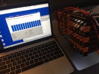
My last two batteries (Hailong 14s4p, EM3ev 14s6p triangle) had balance issues, so I wanted a BMS that would allow continuous monitoring at the cell-row level. The configuration software is straightforward and the serial interface is well documented. This is a photo of the Energus software. I've also been able to build custom apps to monitor charging. I've integrated BMS communication into my custom dashboard that lets me see the high and low cell-row voltages as well as the BMS board temperature and the temperatures of two thermistors.


IMG_2081 2.JPG


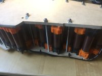
The Vruzend 2.0 caps don't have the compression rods that the 2.1 caps have so I made compression plates from MDF and threaded rods. This took care of my initial cell contact problems. My estimate of the total internal resistance is about 83 mOhms. Compared to my EM3ev 14s6p spotwelded pack measurement of 62 mOhms, this suggests that the contact resistance is acceptable for the Vruzend caps.


IMG_2122.JPG


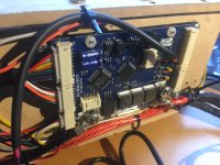
I soldered on very short standoffs so that I could use ring terminals to attach to the board. This makes harness replacements much easier.


IMG_2121.JPG


The next work on the battery will be to use the 2.1 caps to provide robust cell contact and create an acrylic case that is more robust and protects the balance harness wiring better.
 
For the bicycle, I wanted a display that could communicate with both the battery and the controller over a digital protocol. I was especially interested in reading the motor phase current and the cell-row level voltages.

The display has taken many iterations and currently I'm using an Arduino Mega and an Adafruit 1.8 inch TFT display board with buttons and an SD card. It also has a Sparkfun RS485 transceiver and real-time clock.

https://store.arduino.cc/usa/mega-2560-r3
https://www.adafruit.com/product/802

The main screen is a bar graph showing speed, motor current, battery temperature, motor temperature, and the lowest cell voltage. I find simple bar graphs the easiest to read while riding. I also have some text screens for when I want more precise readings, or to monitor the charging voltages and temperatures.

Eventually, I'd like to organize the code to the point where it can form an extensible platform for folks to make displays for their own controllers and BMS. If the devices can be configured with a MODBUS protocol and an RS485 physical bus, each variable (speed, voltage, etc.) can be completely specified by the MODBUS server ID, the address, a scaling factor, and the data type (long, word, etc.). Then, each of these can be displayed in modular ways (bar graph or text).

For now, the dashboard is communicating over a TTL serial UART to the ASI BAC 2000 and over an RS485 interface to the Energus Tiny BMS. Soon, both of these devices will be on a single RS485 bus.

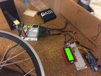
Here is an early prototype using a 4-line LCD display on a breadboard with a Mega.


gen-1-dev-ETC.JPG


This is the first version that I mounted on the bike. It uses a Sparkfun LCD and microcontroller integrated board.


gen-1-bike.JPG


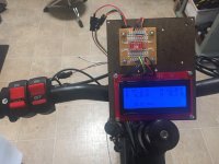
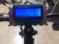
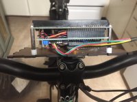
Since I couldn't find a good integrated platform that provided an SD card and buttons, for the second generation, I hand wired buttons and a 4-line LCD.


gen-2-bike-top.JPG
gen-2-bike-side.JPG


Thankfully, I came across the Adafruit display shield with buttons, so this is a much more robust and compact prototype. The only custom wiring is on the green board with the RS485 transceiver and the real-time clock.


gen-3.1-bike-3.JPG


In the future, I'd like to get a larger display and move the 5-way joystick button near the grip so that I can control the dashboard without removing my hands from the bars.
 
Really interesting project ! Especially your custom Arduino / TFT display with data connection to BMS & ASI controller. :thumb:

Personally I find it strange that no other commented on your bike. Especially since this really a different beast compared to the 20th version of a Stealth bike clone running a whoopin 10 kg DD in the rear plus some Adapto or Sabvoton stuff on it. :wink:

Personally I would not go for a screwed battery for such a hub motor monster but it seems that with additional pressure contact resistance is really low.

I would be happy if you post further informations on the progress of your display.

Best regards,
Holgi
 
Have you thought about using the german forumscontroller on you Arduino mega?
 
If you want smooth and awesome wheelies try upgrading to a BAC4000. The 2000 will do 10KW but the torque off the line is really limited by the 144 phase amps or whatever.
 
HolgiB said:
Really interesting project ! Especially your custom Arduino / TFT display with data connection to BMS & ASI controller. :thumb:

Personally I find it strange that no other commented on your bike. Especially since this really a different beast compared to the 20th version of a Stealth bike clone running a whoopin 10 kg DD in the rear plus some Adapto or Sabvoton stuff on it. :wink:

Personally I would not go for a screwed battery for such a hub motor monster but it seems that with additional pressure contact resistance is really low.

I would be happy if you post further informations on the progress of your display.

Best regards,
Holgi

I'm working on an update to the display communication and will post that in the next few weeks. Eventually, I'll post links to the code.
 
guancio said:
Have you thought about using the german forumscontroller on you Arduino mega?

I wasn't aware of the project but it looks very interesting and also feature-rich. I'll look at the code base for ideas.
 
flat tire said:
If you want smooth and awesome wheelies try upgrading to a BAC4000. The 2000 will do 10KW but the torque off the line is really limited by the 144 phase amps or whatever.

A controller that allows a higher phase current is definitely on the upgrade path. The BAC 4000 should double the phase amps compared to my BAC 2000 (~150A to ~300A). In a future post I'll graph the motor current versus the observed torque. My preliminary data looks linear up to 150 amps of motor current with no signs of magnetic saturation so I'm hoping that I can still squeeze some more power to weight ratio from the crystalyte hub motor.
 
drdrs said:
I'm working on an update to the display communication and will post that in the next few weeks. Eventually, I'll post links to the code.
That would be nice ! :thumb:

Although I doubt that I will build my own E-Bike display since I perfectly fine with my CA3, it would be nice to have a closer look.
Since my arduino knowledge is somewhat limited to building simple temperature switches with one-wire external sensors plus solid state relais so far, I might have my problems with more complex code but this is my personal problem. :lol:
 
Back
Top