Custom Kickbike Build (laser cut and welded frame)

michielk

100 mW
Joined
Jun 8, 2017
Messages
38
Hello,

I have build three ebikes so far
- classic steel city bike converted with hub motor, controller and DIY 700wh battery hidden in saddle bags (stealth city use, throttle)
- downhill mtb converted with BBSHD midmotor and DIY 1000wh backpack battery (for hard mtb riding, PAS+throttle)
- full build modern city bike with bafang ultra motor, alu frame, FOX 32 fork, disc brakes etc. (city use, torque sensing)

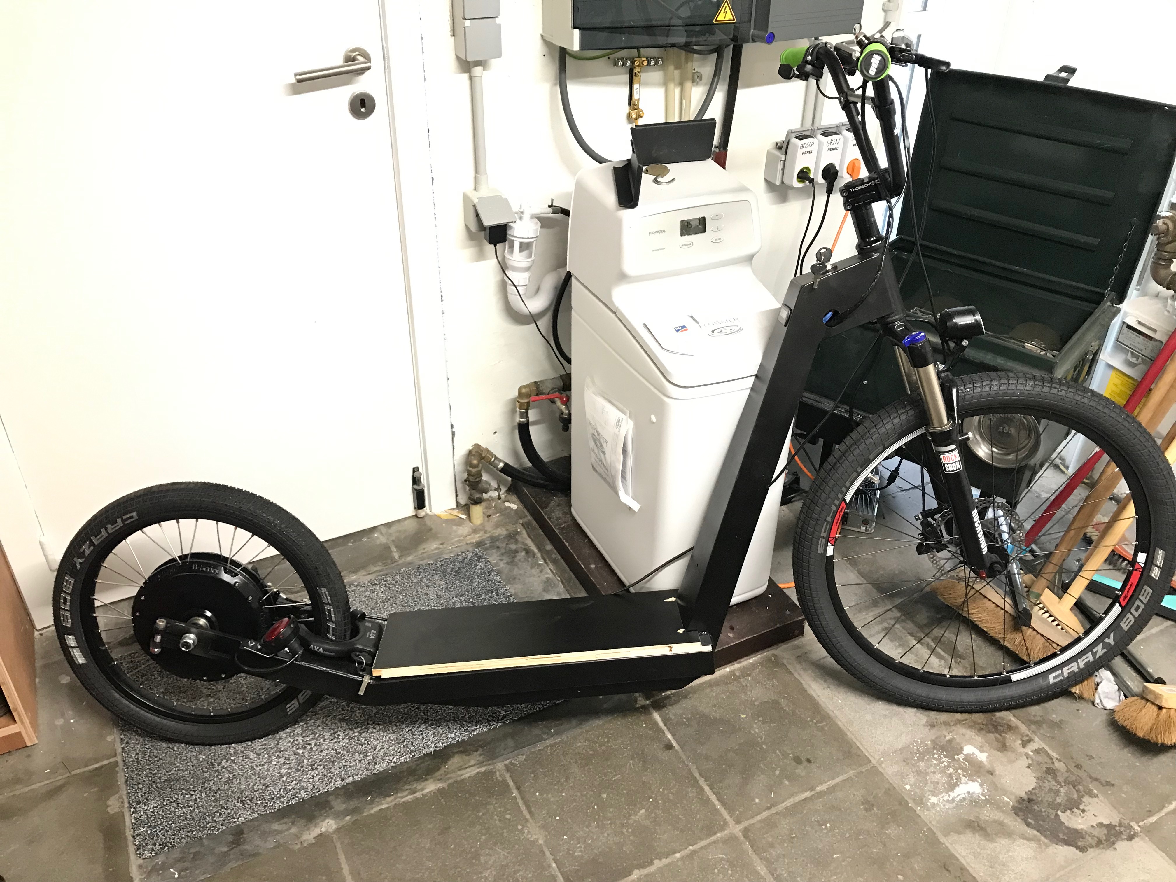
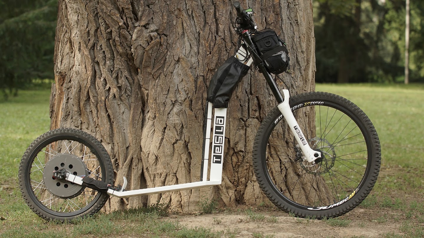
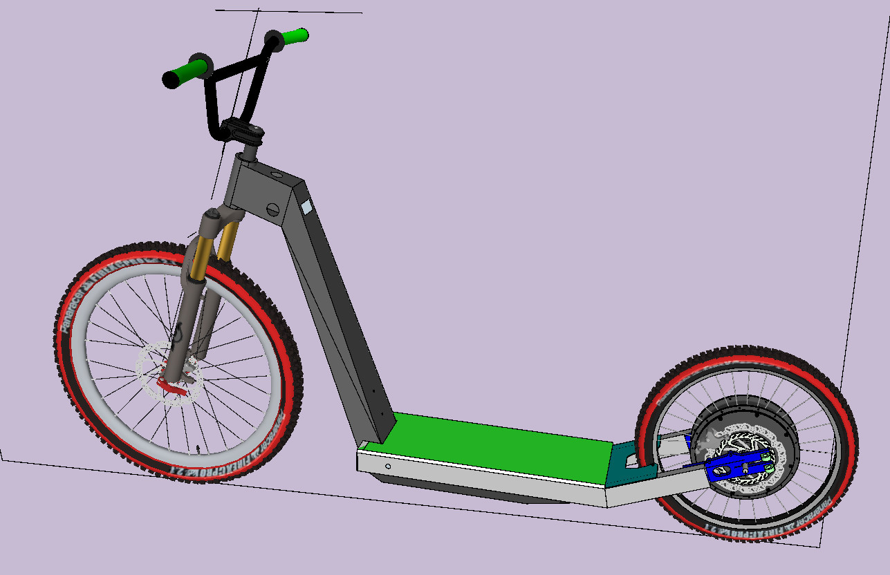
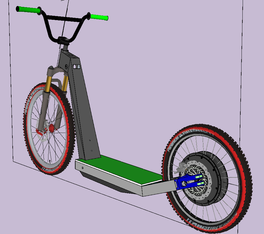
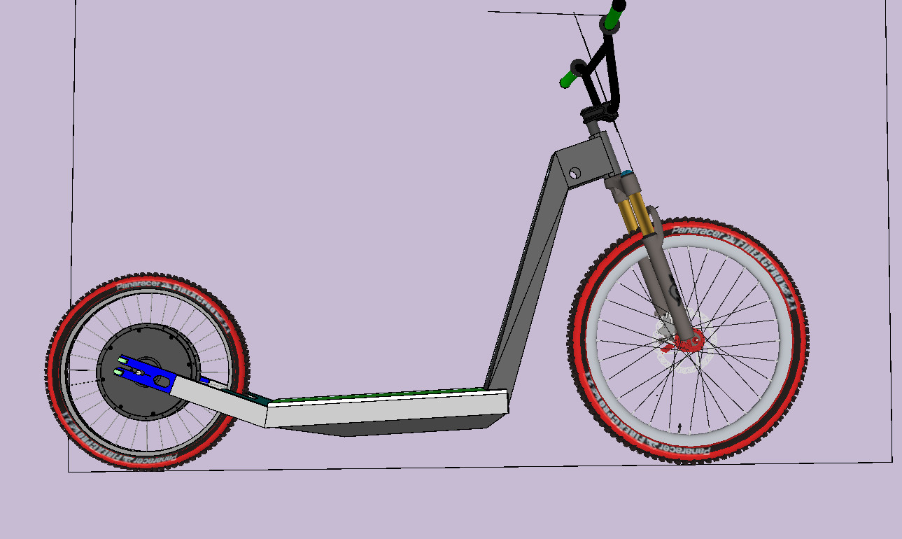
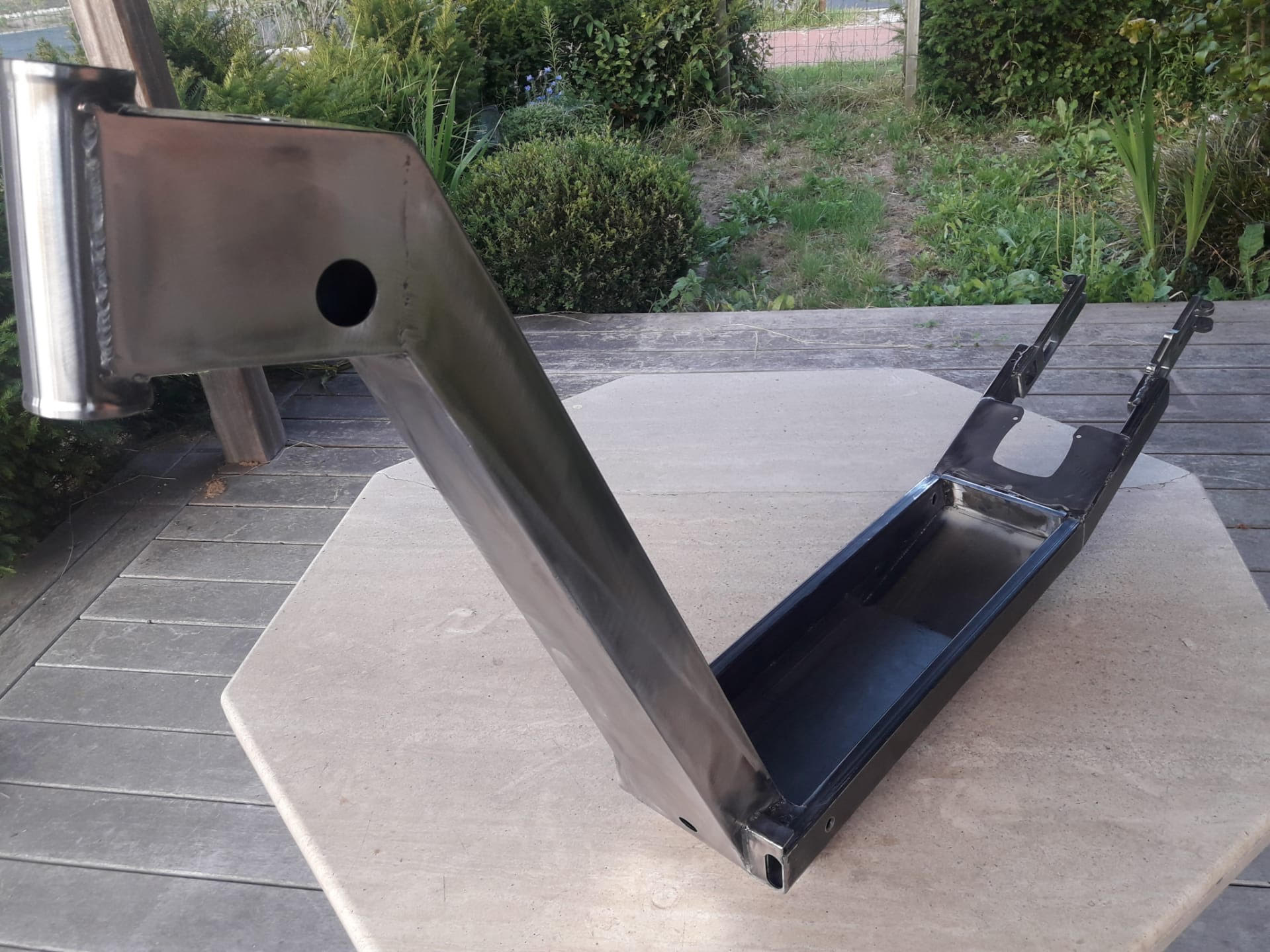
Inspired by this build, I would like to build my own electric kickbike. Different than my previous builds, I want to design and build the frame as well, not just use a donor bike or buy a frame.
0HeZmpS.jpg


My build will have
- hub motor, build for acceleration, not top speed
- front suspension (some cheap basic rockshox)
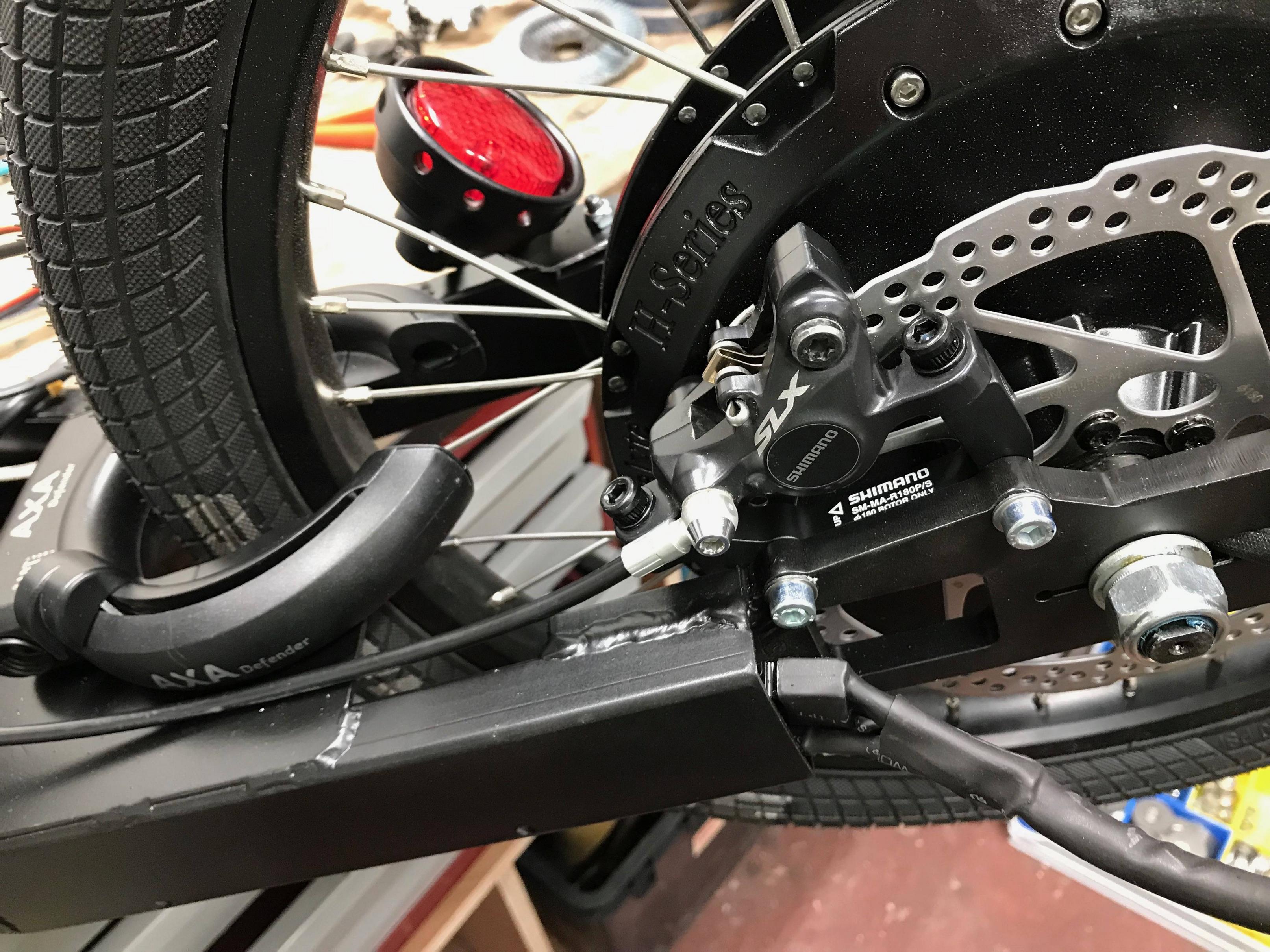
- disc brakes front and rear
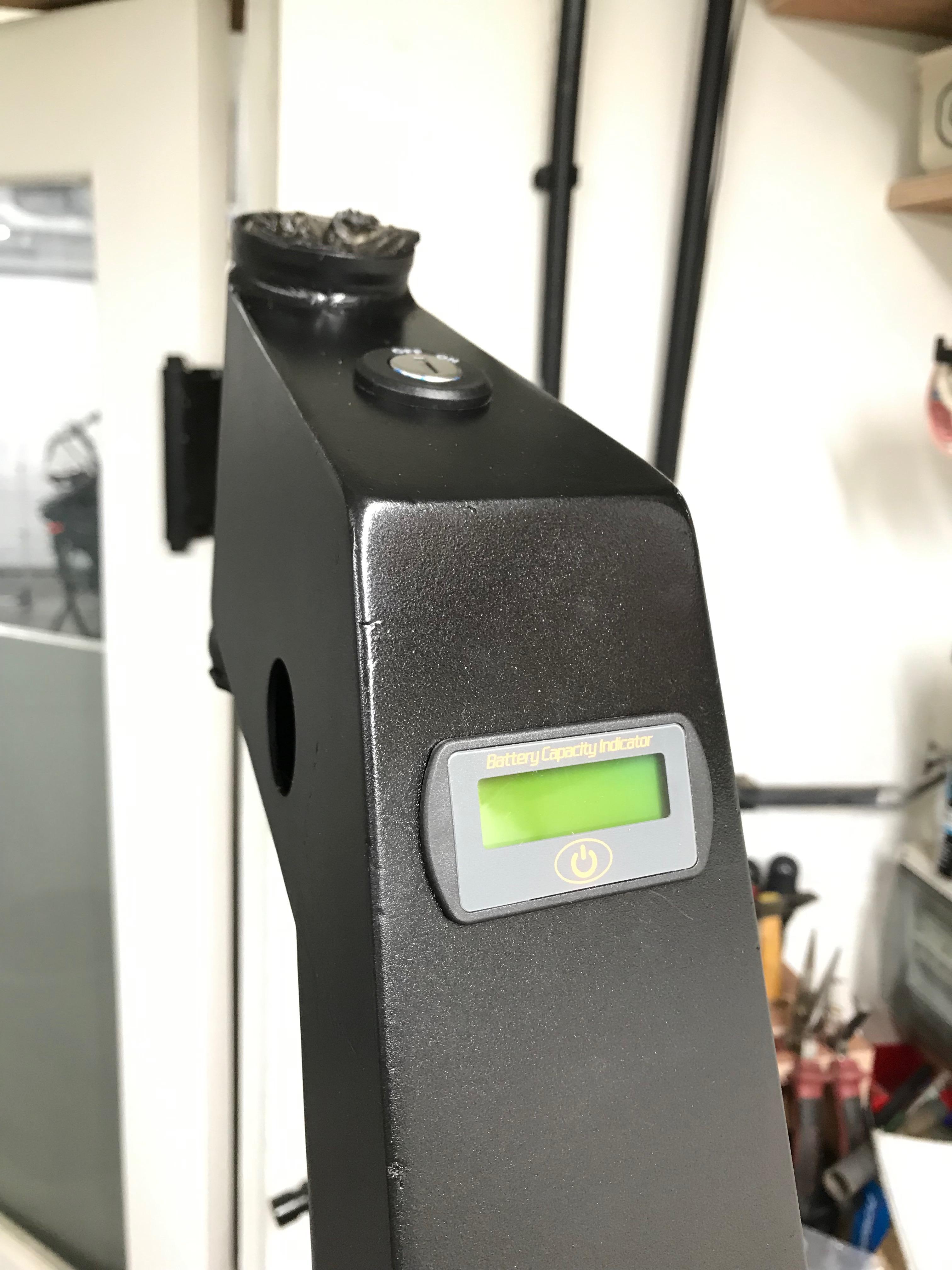
- battery hidden in pan under feet (battery will be bought from EM3EV, no DIY this time)
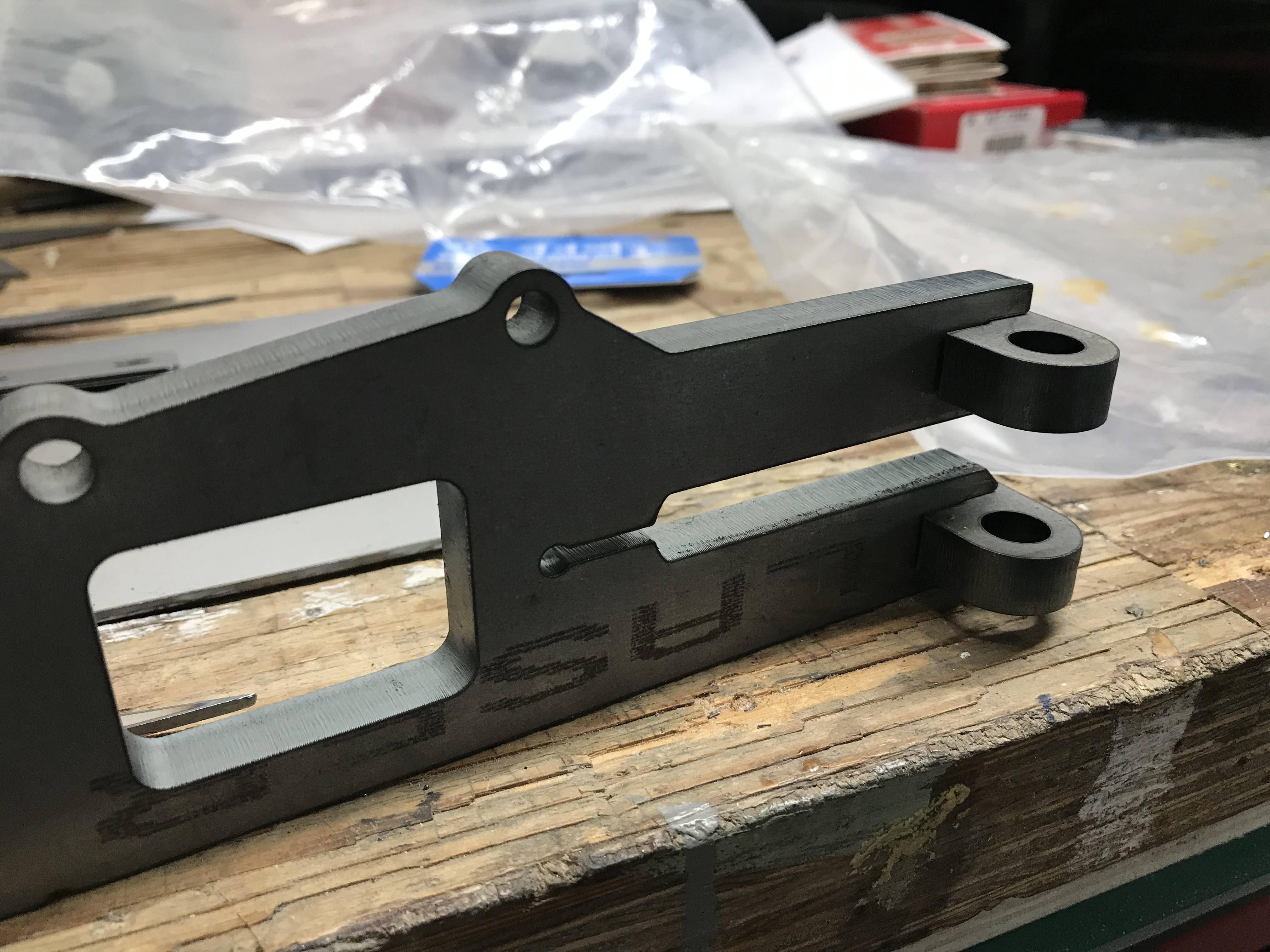
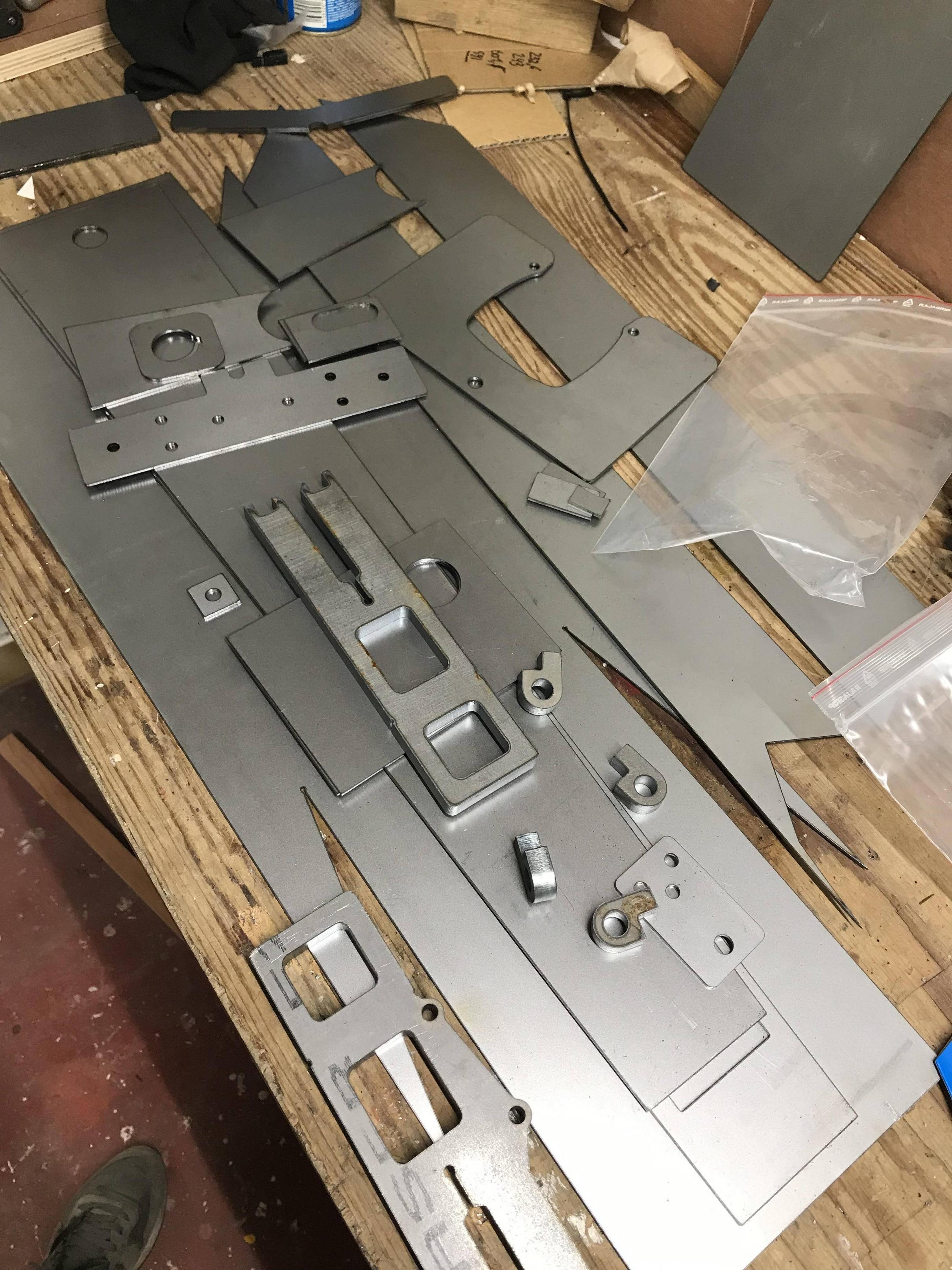
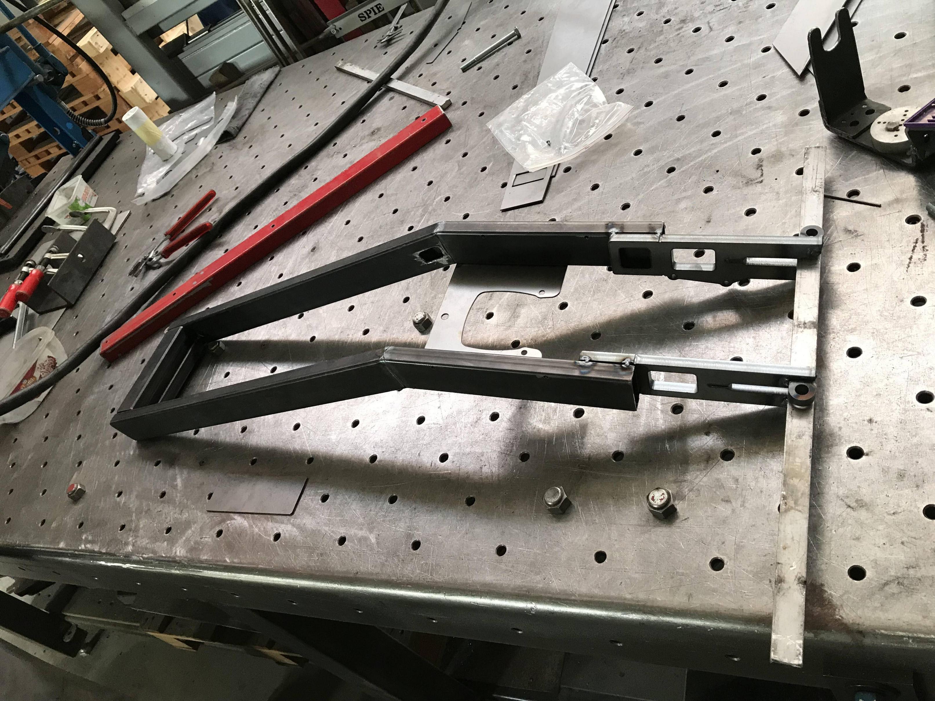
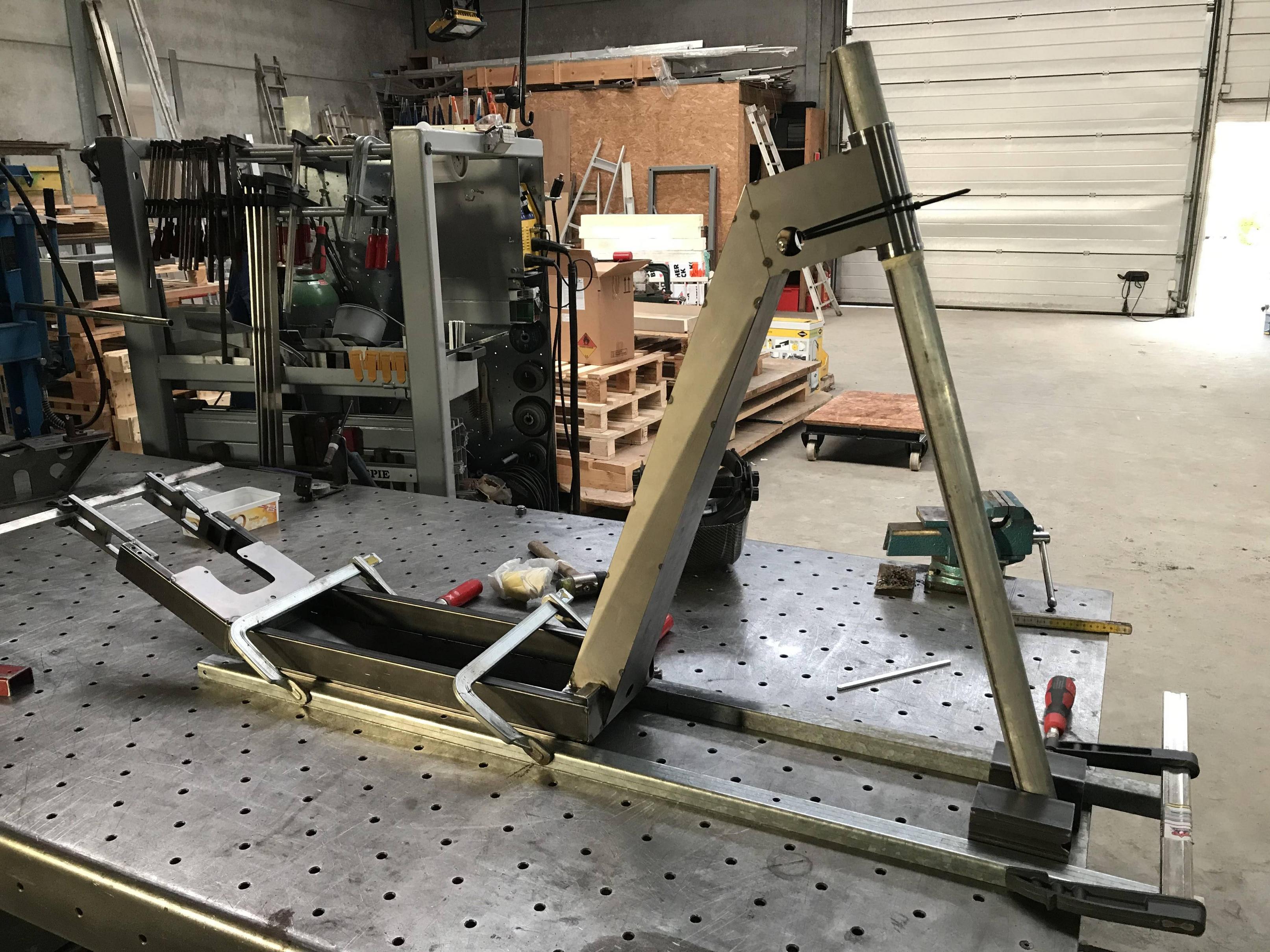
- custom designed and build frame from steel
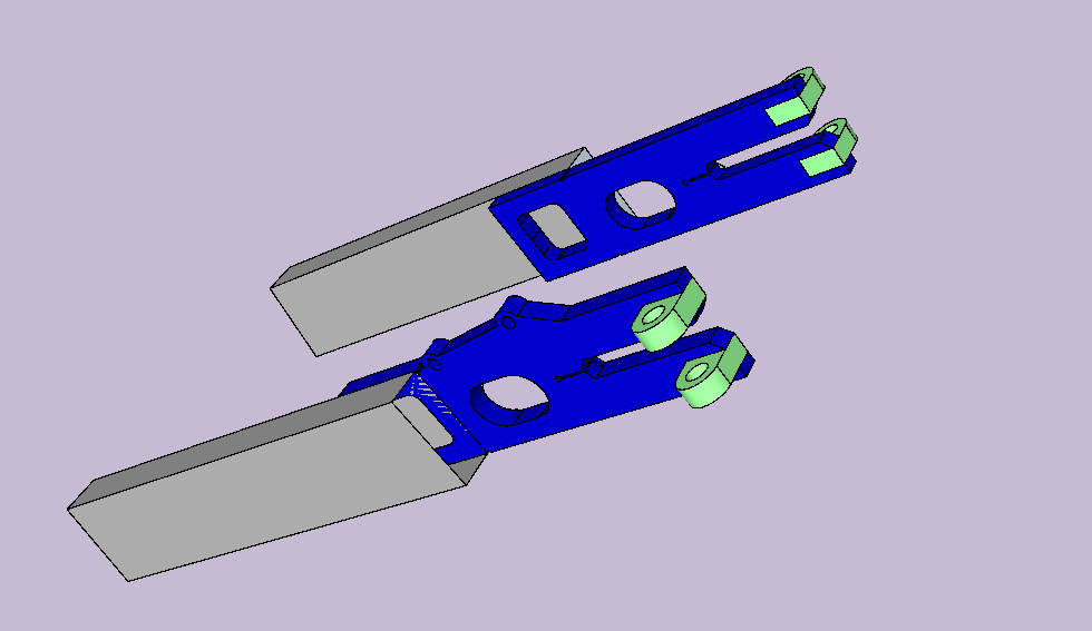
 
The first step is always the design, I went true a few different designs and finally went with this one. I like the setup with a standard 26" mtb front wheel and a smaller 20" rear wheel.

I've had some issues with my first build fitting a strong hub motor in a standard classic steel frame. So now I'm designing my own clamps and going a bit overboard with a 10mm steel laser cut piece and a pinch setup.

ky5BkfN.jpg


Here is the complete bike, for now just in sketchup to design the complete bike. The laser cut frame parts will de drawn in a CAD application later.

rk8ic8e.jpg

3gHVILe.jpg

LHvwmxm.jpg
 
To comply with local law, I would need to kick the bike first before the throttle can be activated. After doing some research and asking on this forum, I think this should be possible using a small arduino micro computer and input from the HALL sensors. Will need to look into this further.

Also, I would like an option to limit the top speed as well. I don't want to use a display on my controller and want to be able to switch easily. So the current plan is to put a potentiometer inline with the throttle. I understand this will limit more than just top speed, but it doesn't matter. I will have the option to bypass the potentiometer with a relay to get max power and top speed.

I would also like to have a front and rear light which I can activate when I want. I would like to just have one button for everything so will use relays controlled by the arduino for all of this. So it will require some design in the electronics department, I don't have any pictures of this yet.
 
The design was finished and I made the drawings for the parts to be laser cut from 2mm and 10mm steel plate.

Heavy duty pinch mount for the hub motor (10mm)
3 parts per side, use a M10 bold to pinch on the flat axle.

P2J5ip6.jpg


Rest of 2mm plate material to form the rest of the frame
oGqHQGo.jpg
 
The frame is made with some standard 20x50mm square tubing for the bottom rails. Bottom rails are cut at angle to lower the pan. And the end of the rails the 10mm pinch plate is welded. On the bottom of the rails a pan is welded with 2mm steel plate. On top is also a 2mm plate for ridgity and to mount a bike lock. There are some 20x50mm square tubes welded between the rails at the front to make it extra strong and to have a solid base to weld the top tube to. The head tube was bought, the top tube is made from 2mm steel parts and welded. Most welds are TIG welded.

wMb9D5x.jpg

0lZ2NHY.jpg

XPX0QUt.jpg
 
Thought about electrolyte coating, powdercoating, .. but will most likely just paint with a decent metal primer and metal paint by hand.
 
Looks interesting :thumb:

I was inspired by your plates for the hub motor, I would want something simular.
But dont you think it would be better to have the clamping bolts as straight behind the cut out as pissible? Maby it does´nt make a lot of difference when tightening nuts on the motor to keep the cut outs strait though.

And I am thinking, why not extend the small cut going forward in to the bigger hole in front of the motor? Then if possible have one small bolt (m6) on ither side to clamp it down?
I think that would keep the motor rock solid in place :) If using a chain sprocket it would be tight with a bolt on the inside on that side, but I think it would be possible. You don´t have a chain, so for you it would be easier.
 
I'm not into kickbikes but this is one of the cooler designs i've seen. Thanks for sharing with us, and good luck with the build :thumb:
 
Finished painting,
wel could use another coat or two, but can't wait anymore to start assembly.

fWLFH3n.jpg


The pinch-plates work wonders. They axle is a snug fit on its own. Tightening the clampd own on the axle makes it rock solid. And adding the bolts on the axle makes it even more solid. This motor is only 3.000W, but I'm confident this mount can handle up to 10x times the power with no issue.

The mount for the hydraulic disc brake is a standard ISO mount, I'm happy that it goes together perfectly. It is my first time designing a part like this and am really happy with how it turned out and that it works perfectly.

The bike lock also fits perfectly.


4gCMaSr.jpg


Laser cutting parts makes it easy to have things look like they came from a factory. Here we can see the keylock on top and the voltage display below that. Both a perfect fit.
 
j bjork said:
Looks interesting :thumb:

I was inspired by your plates for the hub motor, I would want something simular.
But dont you think it would be better to have the clamping bolts as straight behind the cut out as pissible? Maby it does´nt make a lot of difference when tightening nuts on the motor to keep the cut outs strait though.

And I am thinking, why not extend the small cut going forward in to the bigger hole in front of the motor? Then if possible have one small bolt (m6) on ither side to clamp it down?
I think that would keep the motor rock solid in place :) If using a chain sprocket it would be tight with a bolt on the inside on that side, but I think it would be possible. You don´t have a chain, so for you it would be easier.

Thanks for your feedback.
Having the bolts a bit further helps to have leverage on the clamp. It closes it a bit behind. But I'm sure it would work just as well having them closer to the axle.

It is rock solid this way, but I'm sure that would work just as well. Main thing is to have a large clamping area (here 10mm plate) and a way to tighten it down with force. Here the opening is already tight and you can tight it down hard with an M10 bolt on one side. The slight cut is to allow a bit more flex in the part without bending.

The bolts are on the outside, so no issue fitting a chain with this type of mount should you wish. But yes, indeed I don't have chain on this build.
 
neptronix said:
I'm not into kickbikes but this is one of the cooler designs i've seen. Thanks for sharing with us, and good luck with the build :thumb:

Thank you for your kind words.

I know the kickbikes are not so popular around here. But I wanted something different and... this is certainly different! Also, where I live ebikes can only have a PAS system, no throttle allowed. For E-steps, E-kickbikes, etc. this is different. So if I limit the top speed, this would actually be legal on the streets.

For a complete custom build, even the frame, this also seemed a bit easier than a bike.
 
Got everything together. It was a tight fit with all the electronics and large (14S7P) battery, but it worked out. Need to finish some little things, like bleeding the brakes and putting some skateboard tape on the plywood and securing it someway. But was able to take it for a spin. Acceleration is great and everything works as expected.

The clamp on the hub axle is great and really holds it firmly. This can take some serious abuse.

Yt8e71d.jpg
 
that is very impressive, well done! When you modelled it were you able to also model the stresses in the frame? Particularly around the junction where the down tube (?) meets the sort of horizontal bit that holds the head tube.

More pictures of the battery, controller and how they fit in between the bottom rails would also be neat.

Again, congrats, was a pleasure to read about the project.
 
michielk....very nice and quite impressive.

A couple questions please...

A. What head tube angle did you end up with and do you like how it steers as well as the stability at speed?

B. How does it handle with the relatively heavy motor in the rear?

I currently have a Schwinn Shuffle and plan to add a motor in the rear :D .

Thanks
 
This is way over built and heavy with steel and a hub motor, but nice clean lines and proportions. Kudos. I have a similar design planned in aluminum with an outrunner. Stand up rides are cool.
 
Back
Top