Caleb's new build Nine Continent Delta WYE

caleb7777

100 W
Joined
Apr 9, 2009
Messages
186
Location
Smithers, British Columbia, Canada
Well here we go, I will try to document what I can for everyone
Share all my failures for the benefit of all

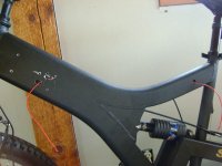
I started with a simple raleigh serengeti i grabbed at Canadian tire.


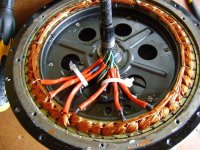
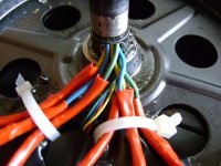
Got a rear nine continent motor by itself from Ampedbikes

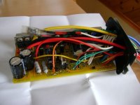
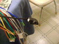
Got an infineon controller from comcycle usa website

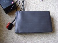
Ordered a 48v 15ah LiFePO4 from ecitypower in china?
(I have not received this battery yet and am waiting for it to arrive before i say they have good products)
more info on battery will be posted here when i get it:
http://endless-sphere.com/forums/viewtopic.php?f=14&t=9054&start=90&hilit=cheap+batt
 
I have modified the infineon about as much as I think I should :twisted:

i have added wires out from SL, CR, BK, X1, X2, DX3, and a 5v+ out
View attachment 3
You can see the temp switch i put in there also, i thought it would be smart to have a temp switch that shorted ground to the Sl jumper so that my output would be dropped to 50%
if the controller got hot but the switch in there is useless as it is a normally closed switch (stupid me).
I want to put in a switch that is normally open and will switch at some temp I am not sure on yet, thinking 40-50. I have no experience with this controller and don't know what heat to expect as safe.
All these wires will go to a switch box at the front of the bike for operation.


Then I added the USB for flashing updates to the programmable controller, very cool.
I use the fact that my bike will be "plug and play" frequently now. :D
I still need to epoxy that USB board and switch etc solid and wrap it in "pro" black electrical tape.
 

Attachments

  • DSC00090.JPG
    DSC00090.JPG
    49.1 KB · Views: 4,062
  • DSC00092.JPG
    DSC00092.JPG
    35.8 KB · Views: 4,059
  • DSC00093.JPG
    DSC00093.JPG
    48 KB · Views: 4,064
I have also modified the motor so that all 3 phase wires go in, thru coils, and back out of the axle so that I can do the delta star switch.
similar to this:
file.php

Of course I forgot to mark which wire was entry side and exit side when sealed it all back up..... I hope it will be easy to determine.


This will be controlled automatically by the Cycle Analyst (CA) so that when I pass the speed at which the motor is most efficient, I can then "shift up" by changing the motor to the delta winding config using a 3pdt relay.
much more info here on delta star switching:
http://endless-sphere.com/forums/viewtopic.php?f=2&t=9215&start=90
 
HAL9000v2.0 said:
I like your shifting idea.
Why is the front wheel mounted backwards?

this is why canadian tire should not be assembling bikes.

-steveo
 
caleb7777 said:
I have also modified the motor so that all 3 phase wires go in, thru coils, and back out of the axle so that I can do the delta star switch.
similar to this:
file.php

Of course I forgot to mark which wire was entry side and exit side when sealed it all back up..... I hope it will be easy to determine.


This will be controlled automatically by the Cycle Analyst (CA) so that when I pass the speed at which the motor is most efficient, I can then "shift up" by changing the motor to the delta winding config using a 3pdt relay.
much more info here on delta star switching:
http://endless-sphere.com/forums/viewtopic.php?f=2&t=9215&start=90


just use a volt tester with tone you can find each phase. your allso wana keep the relays as close to the motor as possible. performance drops if the phase wires are to long.

as you can see i made a relay box. have fun

cheers
 
I have the 3 phases marked, but i realized afterwards I should have marked each end of the phase, green in (original) green out (was terminated originally). I think it might make a difference if I run one coil in the opposite direction? If not great!
 
caleb7777 said:
I have the 3 phases marked, but i realized afterwards I should have marked each end of the phase, green in (original) green out (was terminated originally). I think it might make a difference if I run one coil in the opposite direction? If not great!

If you put the windings in delta and rotate the wheel, there will be a strong resistance if you have any of the windings reversed.
 
thanks, but I am going to open it again and mark everything anyways, but that is good to know.
I want mark the succession also so I will have to open it.

to do that test you would short them like this???
 

Attachments

  • Untitl.jpg
    Untitl.jpg
    19.7 KB · Views: 3,812
I have also opened the Cycle Analyst andadded a jumper across the R6 resistor so that 100mA of current can easily pass through the throttle over ride line. This line will not be going back to my controller, but will rather be used to power relays to switch between delta and star in the motor. The CA will be set so that at a certain speed the line will ground and make the shift automatically. Delta above speed x and Star below speed x.

file.php
 
caleb7777 said:
thanks, but I am going to open it again and mark everything anyways, but that is good to know.
I want mark the succession also so I will have to open it.

to do that test you would short them like this???

Yes, that's the test setup.
If any one phase is reversed, the motor will be shorting and you will have a strong resistance.

If all 3 are reversed, the motor will run OK, just backwards.
 
I had to open the motor again and mark my phases better rather than test many times later.
I just marked off the phase wires I added with a black felt marker

example:
phase a: yellow
phase a': yellow black stripe

Does anyone know which phase wire will correspond to each hook up on the infineon controller, just so that I know ahead of time without trial?
 

Attachments

  • DSC00094.JPG
    DSC00094.JPG
    117 KB · Views: 2,748
  • DSC00098.JPG
    DSC00098.JPG
    74.6 KB · Views: 2,745
I just sealed the motor back up today. Spread a thin film of grease on motor side (where side plate meets) and made thin silicone gasket on cover plate.
Should make it nice and water tight, and the grease will keep the silicone from adhering to the one side so i can open it later if I have to without wrecking the gasket.

I realized though that when re-assembling this motor you have to remove the seal on the plate and put it on afterwards. If you re-assemble the plate with the seal on it deforms and the spring falls out.

I pushed the seal out and added it afterwards, went together much better.

I did both sides and when the silicone is solid tomorrow I get to open it again because the seal on that side is no good since I didn't add it afterwards. (did that side first)
 

Attachments

  • DSC00104.JPG
    DSC00104.JPG
    52.9 KB · Views: 2,725
  • DSC00105.JPG
    DSC00105.JPG
    38.9 KB · Views: 2,722
  • DSC00107.JPG
    DSC00107.JPG
    35.7 KB · Views: 2,721
  • DSC00110.JPG
    DSC00110.JPG
    33.2 KB · Views: 2,723
  • DSC00111.JPG
    DSC00111.JPG
    37.6 KB · Views: 2,720
  • DSC00114.JPG
    DSC00114.JPG
    38.8 KB · Views: 2,718
Here you can see the seal that i did not add after placing the side cover on. It is folded inside and the spring is undoubtedly loose inside. you can see the obvious bulge which should not be there. Run like this the seal would self-destruct!
 

Attachments

  • DSC00115.JPG
    DSC00115.JPG
    29.8 KB · Views: 2,668
  • DSC00116.JPG
    DSC00116.JPG
    41.8 KB · Views: 2,669
me and ryan just finished building the switch box that will be at the front of the bike and hold a minimal 10 switches :D

Any dc-dc converters and circuits will be in it also.
 

Attachments

  • DSC00122.JPG
    DSC00122.JPG
    31.4 KB · Views: 2,618
  • DSC00125.JPG
    DSC00125.JPG
    43.9 KB · Views: 2,615
  • DSC00127.JPG
    DSC00127.JPG
    62.6 KB · Views: 2,617
Started drilling holes to run wires and had an unpleasant surprise.
The frame is actually 2 sections welded together which is great unless you are trying to run wires.
I had to find the middle section so that i could cut away enough to allow wires to pass. There will be 22 wires when I finish....
It concerns me structurally that I am going to have to cut that out but oh well.

I also got the USB adapter working, flashed the controller, and sealed the USB in epoxy and heat shrink. You can see the momentary switch through the heat shrink for flashing.

I am just waiting on parts and for the gurus to help me on the throttle interrupt circuit.
 

Attachments

  • DSC00129.JPG
    DSC00129.JPG
    54.2 KB · Views: 2,577
  • DSC00131.JPG
    DSC00131.JPG
    73.3 KB · Views: 2,575
  • DSC00134.JPG
    DSC00134.JPG
    57.5 KB · Views: 2,573
  • DSC00135.JPG
    DSC00135.JPG
    61.4 KB · Views: 2,571
Got the battery, didn't work, new one on the way. This will slow me down as I need power to work out the phase comination and everything else.
I have seen others use chargers as PSU. Is this fine for test rig? Can I just hook up a 48v SLA charger straight to batt terminals on controller and get this setup?
Is it dangerous to controller?
 
Back
Top