Runabout Upgrade - 20" wide tires Mule with DD hub motor

qwerkus

10 kW
Joined
Jul 22, 2017
Messages
794
After a few builds with mid drives (tsdz2, bbs02) and geared hub motors, I wanted to experiment with DD hubs. There are several reasons behind it, the top ones beeing low noise, low maintenance (NO GEARS) and an additional brake through regen.

Now since its rather mountainous where I live, I first tought that going DD would be pointless - at least until reading here about the power of DD hubs laced in small wheels.

Unfortunately, small diameter wheels come with problems of their own: limited carrying capacity and especially bumpy ride. As a workaround, I figured why not used wider tires ? The increased air volume should help with suspension (see balloon tires effect), and the wider contact surface should improve stability under load.

And thus the idea of a 20" wide tire cargo was born.

At first I wanted to build the frame myself. But since I don't have the welding apparatus, I had to seek for professional help, and, well, given the price tag, had to revert back to the chinese way: find a cheap but decent chinese donor bike and upgrade it.

After some serious searching and mailing around, I stumbled upon this bike which made a good impression. I found the chinese supplier for it, and ordered a sample model. Unfortunately, they would not agree to sell a framekit only, so I had to get the complete ebike with a battery and motor I have no use for....

Took a couple of month, but the bike arrived in good shape.
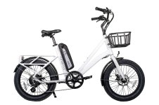
right.jpg

I took a test tour and confirmed my overall impression:

1. 20"x3" is a good compromise. Not as huge as 4" fatties, but still offering a decent suspension

2. Besides the frame, nearly everything is crappy on that bike - from the derailleur to the brakes. The only suprise is the little hengtai motor, proving to be quite powerful; unfortunately it comes coupled with a square wave controller making it super loud. Also, event if the motor has some capacity, climbing steep hills is no option.
 
The next thing to do was to look for a better motor. Criteria where: DD, 1500W max and a lot of torque. Candidates where the infamous leaf motor and the newer 9c RH212. After playing around with the motor simulator on ebikes.ca I figured the RH212 would do, since the few millimeter extra diameter would translate into additional torque. So I went back to alibaba, found the chinese selling them and ordered a fast wound sample. On a side-note, I would have loved to get this one from ebikes.ca, but shipping + taxes from canada to europe are just insane. Too bad as you will see. The order process itself was super fast, but the manufacturer lead time took another month or so until it was shipped. Than, when it finally arrived, I figured I'd lace it immediately, see how it fits into the bike, when this happened:
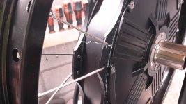
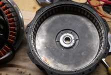
11.jpg

The outer shell just snapped under the tension of the spokes. Huge disappointment. So I mailed the pictures to the manufacturer, who luckily admitted there was a problem with the mold and agreed to replace the unit. After a few mails I also got to understand that this was no isolated problem. I wonder whoelse got a defective shell ? Anyway, the nice thing is that they also agreed to sell me a prototype of the front version, which I was eagerly looking forward to try - more on this in a separate thread.

So a couple of months later, the replacement arrived and this time lacing when fine. Big relief! Notice that finding a strong 50-406 (etro size) rim proved a challenge in itself: the best I could find was a 47-406 double layer rim for monocycles!
 
I wish I could fit a 3.0, I think im a 2.20 on the back tire. I like the 20inch tires, yesterday I had to keep slowing myself down from 45km/h when pulling a trailer and today when I got home I was literally laughing out loud. there was a break in the traffic so I was doing 60km/h hanging a left at the intersection by my house then two wheeling around a corner on my road. that is the mxus 1200w/3005rc from grin technologies
 
goatman said:
I wish I could fit a 3.0, I think im a 2.20 on the back tire. I like the 20inch tires, yesterday I had to keep slowing myself down from 45km/h when pulling a trailer and today when I got home I was literally laughing out loud. there was a break in the traffic so I was doing 60km/h hanging a left at the intersection by my house then two wheeling around a corner on my road. that is the mxus 1200w/3005rc from grin technologies

That's some serious speed. My target is more like 35km/h with 45km/h max on flats. Try to fit 2.4": schwalbe has new 20" super moto x tires of 2.4" dia which are pretty good. Very popular on cargo / trailer bikes. Usually, they fit into regular 20" frames if you remove the fenders.
 
I tried to get holy roller in 20x2.4 but could only get them in 20x2.20 and I should have them from China this upcoming week, I ordered through my local bike shop 5/6 weeks ago and knew Chinese new year and Wuhan was holding up the shipment so atleast theyr shipping out of china again.
 
Since I had to swap the outer shell anyway, I decided to give $$$ ferrofluid a try. Note that the motor arrived with a hole drilled through one of the disc brake screws, so there is actually no need to open it.

ferrofluid.jpg

I injected around 5.5ml. The stuff proves to be insanely liquid; funny how it sticks to the magnets. I guess that means it works. Than I glued the shell with HT silicone back together. The clamp force is very strong so I really would not recommend do it without a proper 3 arm stator puller. Yeah well, didn't have one so I went to old fashion way, which was very violent. I do hope nothing broke through the process...
 
Here are the results of my motor simulation on ebikes.ca:
Fully loaded during climbs
Unloaded on flats

My target is around 25km/h during the climbs, so throttle was set accordingly. According to the sim, climbing the hill should be doable without overheating the motor. Great! Also, top speed unloaded on flats should be just over 45km/h which is my ultimate max anyway. I rarely ride faster than 40km/h, with 35 beeing my sweet optimum in most situations.

Now this is using one of the Grin controller. I don't have one of those, and would rather try a cheap KT controller together with an opensource firmware. I'm a long time *nix user and since the rather slow rpm speed of any DD hub should be no problem for the stm8 chip on that controller, I decided to give it a try. More on this later.

The next thing to decide would be battery voltage. 48V would have been just fine. Yet I wanted to used my favorite battery case again, which is just perfect for 14s 18650, so I dediced to go with 52V. I usually under-charge my batteries anyway to increase life span, so the actual max voltage will be more like 56.7V - so half way between 54.6(13s) and 58.8V(fully loaded 14s)
 
So let's start with the battery. The 48V battery that came with the runabout is actually quite decent. Unfortunately, it's also quite wide (hailong type case: 90mm+) and most importantly has a limited capacity: 13s5p of samsung 29E is not nearly enough for our trips to the mountains, so a larger battery was required. The good news is that I managed resell the original battery - so it wasn't a complete waste.

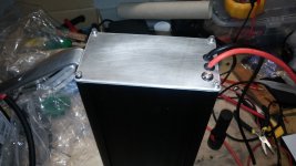
For the new battery, I decided to go with the same casing I used on my bbs02 build. It has a simple square design, is very sturdy and made of solid aluminum. Only major drawback is the price: since I'd discard everything but the body, it's an expensive box!

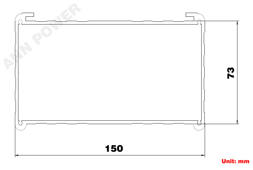
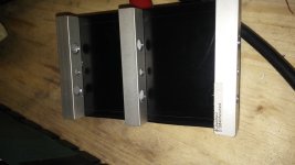
The main body is around 30cm long and here are the inside dimensions:
HTB10k3POXXXXXc2aXXXq6xXFXXX1.jpg


The theoretical max number of cells is 120. I tried a mockup of 14s8p and it barely fits. But I needed space for bolts, cables and such, so I went with 14s7p like last time. The main advantage of this config is the possibility to use a simple square cell holder, which makes welding a lot easier.

The cheapest high capacity cell in europe is the samsung INR18650-35E, so I got a whole load of those (also for my next project) and joined them with 0.2*30mm nickel strips. The whole thing looks very clean and should be able to handle the 60A max for which I dimensioned that battery. Notice that the runabout setup will be limited to 40A max, but I wanted to leave open the possibility to add a second motor or try a more powerful one.

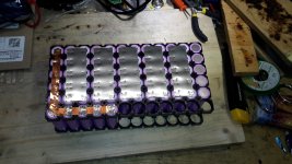
Sadly I lost the pictures of the welding process. Just imagine a car battery, and small arduino welder and a lot of patience. This is a picture taken from another project, which looks quite similar.
20200223_104121.jpg
Again: this is just an illustration to get an idea of how the cells are joined - not an actual picture of the runabout battery

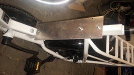
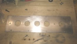
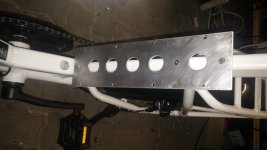
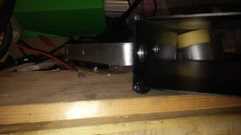
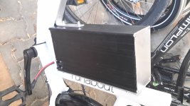
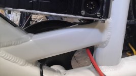
Welding is the easy part. Devising a sturdy way to fasten the (quite heavy) battery is trickier. Due to the frame design of the runabout, using a clamping system would not work. Fortunately, the frame comes with 3x m5 threading welded to the seatpost, which could be re-used to make a new battery support. The Idea is to use a 3mm aluminium plate bolted to the seatpost as a support, and than fasten the battery with 8x tiny m4 bolts onto that plate.

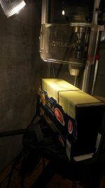
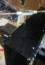
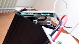
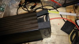
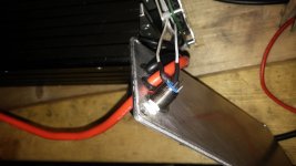
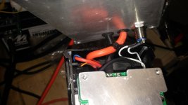
Some pictures of the manufacturing process:

20200207_125630.jpg
20200207_132841.jpg
20200207_161817.jpg
20200207_164910.jpg
20200207_175832.jpg
20200207_180312.jpg

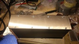
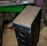
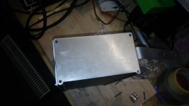
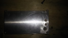
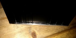
I also got rid of the annoying plastic covers and made new cover plates of of plain aluminum. 2mm for the top and 3mm for the bottom.

20200209_112425.jpg
20200209_112433.jpg

Now after test fitting the case, I realized that the 3x M5 seatpost bolts might not be strong enough against lateral shocks, like when you'd hit the battery with you foot upon mounting the bike. After all, the battery is 150mm deep. So I made a second bracket out of a 4x20mm aluminium bar bent to fit onto the front of the battery and the bottle mounting threads of the frame. Bending thick aluminium is quite ugly - not sure how strong this will be, but it seems to work just fine.

20200209_112452.jpg
 
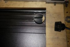
The next job would be to prep the output for cables and charging ports, plus an ON/OFF button.
Here the hole for the rosenberger charge socket:
20200209_143640.jpg
20200209_153647.jpg
Tight, but fits: 6mm diameter is enough for a ruber grommet + 10awg cable.
20200209_155615.jpg

I chose to put the charge port on the lower left side of the box, where it would the least interfere with leg movement. This proved quite problematic, as I had to build a spacer to avoid the cell pack crushing the ropd charge port.

20200215_174753.jpg

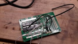
Prepping the bms. I used one of those JBD smart BMS, mainly because of the on/off switch and the possibility to manually set battery parameters like max charging voltage and balancing via the computer app. That BMS is rated for 60A and perfectly fits into the box. Only problem are the side connectors for temp sensors, so I soldered them directly to the board. I had some troubles with the power switch not working, until I figured out it was a cold solder joint :oops: .

20200216_151112.jpg

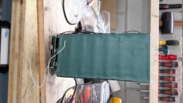
Pack kapton taped and fish paper covered all stacked up to check total height.

20200216_163635.jpg

Seems to fit, so shrink wrap is added. the bms stays outside the wrap and will directly touch the bottom aluminium plate for better head dissipation.

20200216_164337.jpg

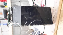
Squeezing everything in. Notice how the negative battery cable goes through specially drilled holes in the spacer.

20200217_102454.jpg20200219_152823.jpg20200219_155133.jpg

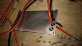
Added some sort of tension relief to the main discharge cables. Yeah, just a zip tie...

20200219_155451.jpg

Case edge is properly siliconed before final assembly.

20200219_162840.jpg20200219_162846.jpg

Looking good!

20200220_154224.jpg20200220_154237.jpg
 
goatman said:
that is a nice tight fit, im just curious, is all the battery weight sitting on the bms?

Given the backwards inclination of the seatpost (18°), I'd say around 95% (cos18°) of the cell weight is indeed pushing against the bms. I have no idea if it's possible to crush the MOSFETs but I did some test using a 10kg load on top of the bms, and it didn't flinch, so I guess the actual 5Kg (49g*98cells + nickel/wires/insulation) are ok too. The problem is the charge port: I wanted it on the lower back side of the case so it wouldn't interfere with leg movement (there is a rubber cap covering it which protrudes by another 8mm) and with that placement, there is no option but to put the bms next to it. Should something break, I'd have to get a new case and drill new holes to flip it over, with the bms on top of the case.
On the plus side this way the aluminium cover of the bms is tightly pushed against the 3mm aluminium bottom plate of the case for optimal heat transfer, and all wires are kept to a minimal length.
 
I saw you had drilled 3 holes in the square tubing where you have thick wire running, I thought the other two were getting rodded through the case, holding the weight off the bms but I didn't see any nuts on the outside of the case. I was just curious the bms does have those stand off things. nice build.
 
goatman said:
I saw you had drilled 3 holes in the square tubing where you have thick wire running, I thought the other two were getting rodded through the case, holding the weight off the bms but I didn't see any nuts on the outside of the case. I was just curious the bms does have those stand off things. nice build.

Yeah: first I had the bms sitting on top of the cells, so I needed 3 holes to route the thick wires (+,- and charge). Than I moved the charge port to the bottom of the case and the bms had to follow.
 
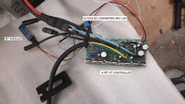
Update. It tried to run the motor plugged to a kt controller flash with the open source firmware and failed miserably. Burned 2 controllers: 1x 9fet and 1x 12fet. Arguably the 9fet version is not officially supported by the firmware, but what I don't understand is how the 12Fet controller cooked. I used a proven 12fet dd settings tweaked to my small wheels and voltage / current settings, and as soon as I switched the device on: BOOM - fets exploded! My my my... not what I was expected. I ordered a new set of controllers but will probably stick to the stock firmware, if I manage to configure it properly.

I a picture of the setup taken just before the explosion
controller.jpg

The BT + OSec App worked fine on the 9Fet controller, but I could not get it right on the 12Fet controller. Maybe there was some file corruption during compilation / flashing ?
 
Back
Top