Kids Cruzee ebike build during lockdown

Jimbaloosh

1 mW
Joined
Apr 13, 2020
Messages
10
Location
Durban, South Africa
So in South Africa we are having a pretty serious lockdown. You can get shot at and arrested for being outdoors in some areas. So one of the projects was to build an ebike for my 3 year old kid.
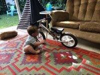
He has a Cruzee balance bike and a FIT 12" BMX. Size wise he's kinda in-between the two.
So parts wise lying around I had a brushless turnigy 6365 270kv. The old gold and silver ones. A hobbywing quikrun 120 Esc a few servo testers and some 3s lipos.
0B2AA28C-CA4E-46B5-9EE9-8F48964A1A33.jpeg
https://www.instagram.com/p/B-zvC1_pMrQ
 
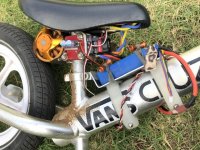
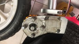
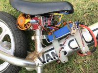
So first thing to do was to hold the motor and figure how to attach it. I wanted to go belt drive but there was nowhere to get a belt as all the shops are closed.
So I decided that friction against the back tire was an easy way to get it going to start with.
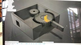
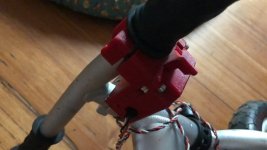
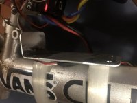
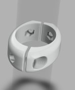
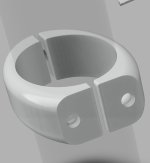
There was a bit of space below the seat where it could just squeeze in. So next step was to thumb suck the position and draw up the parts in Fusion360. I printed the seat clamp on the 3d printer and the plate pattern onto paper and checked that it should work. It seemed ok so I stuck the paper onto some 12mm Ali plate and drilled/ machined it out. Put the parts together and hey presto it all kinda fitted.
B1735EEA-A7F7-4E84-9015-EC8C4BFF78EA.jpeg
048E1A53-8188-4302-9B30-A8634C34B987.jpeg
79D432B5-66D8-4142-AD84-55054CAFBD40.jpeg
 
Next step was to connect a RC receiver to test it all worked. I started with a 2s battery to be safe and just edged on the power as he pushed along like normal. The motor spun against the tire and lost slot of power and pushing it down hard just killed any efficiency that the system had. But it worked. He rode it. It moved. And nothing let the smoke out. 😊
His little brother was amped too. 🤘🏼

7CACB70A-DED0-4399-95F0-BCF688D28973.jpeg
 
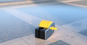
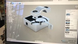
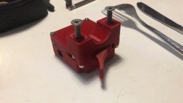
The next step was probably my favorite. Asuch fun as it was controlling his speed from my side he needed a throttle. I'm not sure what the concensis is regarding thumb vs twist. But I decided to go thumb. Back to fusion360 to draw up a housing that will hold a servo tester and let it be driven by a thumb lever. First version was functional but like all my designs I didn't leave quite enough tolerance. It worked fine with a bit of sanding but I also wanted to put in captive nuts instead of printing the threads on the bigger bolts.

Here's the file:
https://www.thingiverse.com/thing:4270258

D278AE53-0D31-407A-8FAA-FC111BC1ED05.jpegA39C5A9D-28E6-46FA-AC8C-F141FE6B1636.jpegDAA75CDA-3AE5-4BE6-8B79-CC8305DD7C10.jpegC494EE4A-C444-47B7-9E21-62B9B382E14E.jpeg
 
So now the thing was going pretty well. He got the hang of the throttle almost immediately. Only one whiskey throttle out the doorway. 😂😂😂
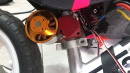
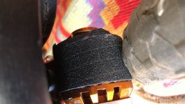
We rode like this for a few days then decided that we need to make it way more efficient. So I managed to ughle in a sheet of skateboard griptape that I cut into a thin strip and wound around the motor shell. Aost immediately there was a big difference but I realised that Eddie is just gonna tear some flat spots in the tire from gassing it to hard.
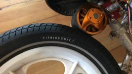
I'd orderd him a 12" FIT BMX that is still too high for him but it has propper tyres and tubes. Bingo. As soon as this was on it was a different beast all together. And it now had waaaaaaay less rolling resistance after the crappy foam tires. This was the winning combo and I'm 99% happy with the drive train right now.

The only change i'd do is give a wee bit more space between the motor and the clampy part. It hits fits with the griptape but get jammed up easily if he's riding through wet dirt. Or even just some sand after wet grass.

0CD6ADB6-107F-4FBE-B985-A97AA1D55EC7.jpegFDCC8168-4DFE-4DED-80CE-5621395D82AD.jpeg
 
To keep it all vaguely respectable I need to keep the battery safe. The way he thrashes the bike already there was no way the battery was going under the sowntube. And it didn't like balancing on top. So i printed some brackets that would fit snug onto the frame and cut a piece of Ali to be a battery mount the plate. I put a 90 degree in the end so the battery wouldn't slide off. And gonna get Velcro to keep it snug.

D24D0180-0E10-45B7-B40D-82B27B5267E9.jpeg67AD4A17-400C-4750-9C23-3494EA14C8B9.jpeg4029B50B-9A32-4690-A8CF-D43BD3E872AB.jpeg7B2CC231-82B6-4C14-9A6C-405131826A07.jpeg
 
Awesome build ! A++

Your boy is one happy customer !

I like his attitude. Fall off ? No worries. Have a laugh. Give it another go. Champion !
 
Thanks Mr serious. He's pretty stoked.

So next thing is to make some pedals/footpegs.
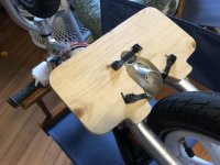
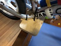
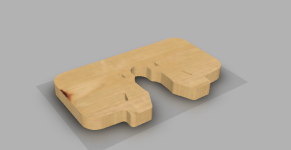
I did make a version a while ago but they weren't right. So out with a piece of card and roughed out a design with a pair of scissors.

Chucked that in the scanner and then once again back to fusion360, goddam I love that piece of software, Drew them up then popped it in the CNC machine to cut it out.
I am planning on using up more of the sheet of skateboard griptape once I'm happy with the design.

And the cable ties are sure lowfi, but I can't think of a simpler method. 🤷🏻‍♂️

A6D57937-F407-4692-BB37-E09FBF47434B.jpeg3E8B842E-4CBF-4A19-9080-B06D1A23D0DD.jpegC9BD9DAA-7035-4ED8-84B3-0B9BF67C9EE7.png
 
So time to address the elephant in the room.

This thing hauls ass and to be a responsible parent and ensure a slight modicum of safety I guess brakes are maybe a good idea.

Ok so options were:

Mechanical,
Pros: They are tried and tested, nobody will question them, they will work with the power off.
Cons: Wont be nice for 3 years old fingers to pull, super inefficient, don't have parts during lockdown.

Electrical:
Pros: Wont add weight, slick, fun to try figure out how to do, can print the lever,
Cons: I have no idea what i'm doing with electronics, i may / may not have the parts here? Don't work with power off.

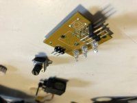
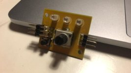
So first step was to figure out if this was possible, i have a vague idea how servo signals work from years of RC. I had a spare servo tester lying around so i thought it'll e better to fry that one that blow up the one in his bike. So a servo tester has a pot that gives a varying resistance and a little brain that sees that voltage drop and converts it to PWM that the esc understands. Its not at all like the hall effect system that ebikes normally use.

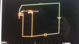
First thing research, i found a post about a guy wanting to put a dual rate knob onto a rc car remote, so went down that rabbit hole and read up on putting pots in series and parallel, but could get my head around it until i found this site.
http://www.falstad.com/circuit/ the guys that made this deserve a big ol high five (one we rid of this Covid19 situation)

I need to gibe a big thanks to my friend Mark Beets for putting up with my endless questions about circuitry.

This gadget is absolutely amazing and it was so nice to be able to figure out what i need to do.
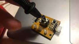
Started off measuring the pot in the servo tester at 10k ohms so drew that into the app, then added switches and an ohm meter to figure out firstly what happens when you adjust the pot, then secondly how to cheat the circuit into doing what we want.
i dug through my boxes of old crap and found 3 resistors, tester them and they were 217 ohms each. so popped that into the app and very luckily they were the perfect resistance to cheat the circuit into thinking the pot was turned to almost full brake!!!!!!

So quick interlude, RC car ESC's work like this:
0- middle is from full reverse to neutral, middle to full is throttle. ESC wont arm if the position isn't middle when it turns on.
so we had the middle to full throttle sorted but needed to have away to make it brake.
most esc's you can set to reverse/forward, reverse/brake/forward or brake/forward. that option was the win for us.

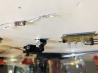
At first i though id have to have a SPDT switch that disconnected the normal pot and switched over to the "brake" circuit, but i realised that we didn't need to kill the original circuit, we could just jump ontop of it, not sure it thats proper electronics terminology. but if we jumped from the input to wiper of the pot with one of the resistors it's perfect to be full brake without disconnecting the pot!!! bingo.

So next stage was solder in the wires and resistor (which i learnt can be used both ways) and we managed to liberate a tiny push button momentary switch from the fried servo tester.
The switch is tiny with a 6mm square base and a 3mm button on top.
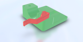
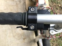
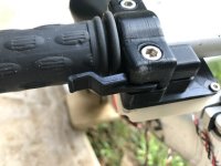
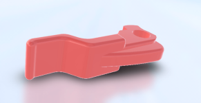
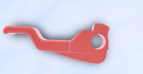
So back into fusion360 :) and time to draw a brake lever that will integrate with his current throttle body. gotta keep back brake on the right...
AF57297C-8B8B-4893-8536-1ABC08390049.jpegA6F0FFB5-CF57-4669-8140-74654C1CDC89.jpeg97B3B455-9356-4B9B-9877-F24A3A6BC59C.png
1F04EBD1-0E41-41BD-BC4E-95FD2AB60074.jpegEDDF1096-E5BB-4CFC-9D8B-44E7D75DCEF7.jpegBAA906B7-40A1-4FE7-9E4C-5A0111B46277.jpeg
 
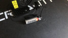
9A7FD74A-9F01-48D9-93E9-DE43295AA6BF.jpegSo the brakes worked an absolute treat. So stoked. Only issue was I made the lever a bit to small, I do get lost in the scale when in fusion360. It does help to have the bars and grip modeled too. But still it came out tiny, much smaller than an AA battery. I had to also redraw the lid and top clamp of the throttle assembly to accept the lever spring and switch.
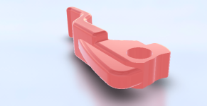
I redrew the lever again and printed out a slightly beefier version, but still tiny. I guess it’s ok being small. His hands are still tiny and we don’t need much leverage. We’re not pulling a mechanical cable here. Just pressing a tiny switch.

In terms of the effectiveness of the electronic braking. It’s amazing. Feels like full abs. Just shy of locking up at any speed on any surface. Cant wait for him to have more space to ride this thing.

In regards to the foot pegs. I’m not 100% convinced by my design. I may make some much smaller. More like typical motorbike ones that will sit under the arches of his foot.

21E3D2CB-4509-4DF6-948F-E023ED89724B.jpeg845EBC69-C37A-4563-AB81-3FC432076BDA.jpeg
7013DB4A-EF06-4508-A3A2-4C8C0A3EA0B1.png46A3F276-3B43-4AD0-AC80-2FB133140489.pngF57D5768-BECA-4FF9-A132-47D6A11BD42A.png
 
Back
Top