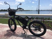
Meet Miss Mino'aka

kauaicycler

Administrator
Joined
May 18, 2019
Messages
176
Location
Cocoa, FL
file.php

Mino'aka as a Baby
The big thing in the middle is a lock


All parts are brand new and build work is performed by me (except as noted) in my garage with the bike upside down as needed in lieu of a work stand.

  • DONOR BIKE: Electra Lux 7D Fat Tire
  • MOTOR: BBSHD Kit
  • BATTERY: 52v 20ah Triangle Battery

I decided to do a mid drive install because it offered the most flexibility for different terrains as I was unsure where this bike might end up. I chose this particular bike based on the following reasons.

  • Available at a local bike shop.
  • Pedal forward design for more upright posture.
  • Disc brakes
  • Fat tires
  • Lightweight Aluminum frame
  • Large frame size and wheel base
  • Well documented builds as both BBSHD and Leaf hubs.

Most of the hard stuff related to this build are covered in the excellent posts and articles linked to here. My documentation is about the stuff that wasn't mentioned or was unclear to me as a new builder and biker. It's also my amalgamation of different best practices and tips to building a reliable, durable and clean looking ebike.
 
As per the posts I've seen it was possible to mount the mid drive upside down in the frame triangle. This seemed like an awesome idea as it put the motor above the bottom bracket and increased the ground clearance. It also made the ebike a little stealthier. This decision did have some cons to it though. In order to do this I needed to cut off the tab on the top of the bottom bracket that supported the chain guard and I had to make room in the frame for the motor. At the time of this build I didn't have access to the tools needed to cut the chain guard tab or make room in the frame to fit the motor.

I decided that the best way to make room in the frame was to dimple the frame just enough so the motor would fit. I saw two different methods to accomplish this. One guy made a nice little rig that he could use to squeeze a dimple into the frame, the other guy used a hammer. I liked the squeeze idea as it seemed to offer the most control but I lacked the tools for this. It's good to have friends.

Enter Jerry; Jerry is a mechanic friend of mine here in Florida who also builds airboats and raced motorcycles when he was younger. I've talked to him about my upcoming build and he was interested in ebikes when I mentioned how they could be useful for hunting. I knew he had the tools but asking a professional mechanic to borrow tools is very bold and would only partially solve this problem, I would still have to do the cutting and dimpling with no experience working with aluminum. I explained everything to Jerry with pictures and he offered to help.

I removed the bottom bracket with the help of this article Mid Drive Kit Install Part-1, Removing Bottom Bracket Cartridge, took the tires off my bike since they would have to come off anyway and grabbed the motor and my phone with lots of pictures and headed to Jerry's. The first thing we had to do was cut off the chainguard tab. As I held the frame steady on a block of wood, Jerry cut into my brand new bike with an angle grinder. That pain was nothing as I flinched with every hammer stroke when he decided the best way to dimple my frame was with a pair of hammers. The pain quickly subsided though as we successfully mounted the motor into the bottom bracket.

There was one other step that I didn't find much information about and that was how to properly torque the lock rings used to secure the BBSHD to the bottom bracket. One of the first tools I bought for this project was a torque wrench Bike Torque Wrench 1/4 Inch so I wouldn't destroy my aluminum frame by applying too much torque. Of course a torque wrench doesn't fit on a lock ring and the wrench I had was for smaller bicycle sized components. In my search for a way to install the lock rings I found many special wrenches and even a few very expensive sockets that would fit a torque wrench. I opted for the cheap flat wrenches BAFANG E-Bike BBS Wrench and the click in Jerry's sensitive elbow to get the right torque. I believe there are ways to attach a torque wrench to a flat wrench like this but that's a whole other post.

I wanted to pay Jerry for his time because he is a professional and we did this at his shop but all he wanted was a ride when it was done. With that settled I packed the bike up to take home and was ready to begin the rest of the build from my garage.
 
This was the most challenging and rewarding part of my build. I had a huge triangle battery to mount to a frame that didn't have a triangle. I've read where other builders using this frame have just suspended the battery in the frame by the battery bag straps. This might be fine for experienced builders but it was too much of a stress factor for me. I had too many unknowns to deal with let alone a dangling battery (did I mention I'm in Florida LOL;). After scouring the Internet for ways to attach batteries to bikes I came across a builder who used pipe clamps to attach things to his bike. I made some measurements and off to Lowes I went.

Most of my DIY projects have been computer centric so Lowes, and home building supplies in general, is not a familiar place. Being as this was during the pandemic I wanted to be in and out as fast as possible and talk to as few people as possible. I had my measurements and a list of parts needed for my build such as heat shrink, electric tape, dielectric grease, hose clamps, spray paint, zip ties, scotch guard, and cable cutters etc. I managed to find most of what I had on my list without help. Now I needed to be inventive.

I had decided through measurements that I could make a shelf of sorts from the seat post tube to the headset tube that would emulate a regular bike's down tube to mount my battery to. The shelfs width was determined by the width of the two tubes that joined the headset of my bike which was 2 1/2" and the length needed to be long enough to fit the battery. I flipped the bike upside down and placed the battery against the top top and seatpost tube. I could then determine how far up the seat tube the shelf could be mounted. This let me determine the length at around 19". I needed something about 2 1/2" x 19" that I could attach to the pipe clamps and fasten to my bike.

I have all of the items on my list plus extras in case I had the wrong sizes and had to wander the store looking for that shelve thing. It occurred to me that there might be some sort of pre made shelf that would fit. I was looking for something strong, lightweight and waterproof and was the right size. I eventually stumbled on this bracket CLOSETMAID 5660500 20" Shelf Bracket made as part of a set that looked like a suitable support. It was steel and u-shaped and the perfect length with a mounting that was at the perfect angle to reach the head tube. It was too skinny to support the whole battery but I figured I could attach something to the top. What that would be wasn't determined and nothing in the shelve section suited my needs. I thought something plastic might be good so I went searching for that when I discovered the glass and window section which has Lexan. Lexan is a clear polycarbonate that is strong, lightweight and waterproof. Perfect! Only problem is that they were out of stock due to the high demand as retail shields for the pandemic. I found nothing else suitable so I left with what I had.

While contemplating how I would attach my shelf to the bracket I considered various clamps and such but then I had the inspiration to use epoxy. This seemed more elegant as I didn't have to drill or cut into anything. I also felt that the epoxy along the whole length would make a stronger connection, it would reinforce the strength of the bracket and produce a cleaner look. With my new idea I headed to Home Depot where I found this sheet of lexan 24 in. x 18 in. x 0.093 in. Polycarbonate Sheet some Kwik Weld epoxy, a bag of 3/4" hose clamps and some flat black primer spray paint that matches my bike.

With all of my parts acquired I was ready to build this thing. My first step was to flatten the top of the bracket and open all of the hose clamps so I could paint the bracket and hose clamps. Next I needed to cut the lexan to a 2 1/2" x 19" strip. I searched youtube for videos of how to cut plastic and found this video How To Cut Acrylic Sheet By Hand. I was going to attempt the scoring method outlined in the video when my brother-in-law offered a rotary tool he had for my use. I still thought the scoring method might produce a cleaner edge but I didn't have any suitable clamps so I went with the rotary tool.

The rotary tool was a godsend and made the whole project easier and more professional looking. The kit he loaned me had no cutting wheels so I ordered this set from Amazon Cutting Wheel Set. I wasn't sure what wheel to use so I just grabbed one of the diamond wheels, I think. Cutting a straight line wasn't as hard as I thought. Unfortunately I cut it too short, oh well that was my practice cut. I turned the plastic sheet around so I would have at least one straight edge and cut another piece. This one came out the right length and the cut was a little bit straighter. I took both pieces and used my cement driveway as a large flat file and rubbed both pieces flat. I then smoothed both pieces with sandpaper and painted them.

I was originally going to glue everything together on my workbench but I found I could get a better placement if I mounted the bracket on the bike before gluing the shelf to the bracket. First I cut a piece at the base of the bracket to let the motor cable out. I had to order a longer cable to reach my handlebars since the bike is so long here's the cable I ordered from Amazon 1T4 Cable for Bafang I flipped the bike on the handlebars and strapped the battery to the top and seat tube to fit the placement of the battery one final time before mounting. I marked the position and I removed the battery.

I then used three painted hose clamps at the base of the bracket and on at the top. I placed pieces of rubber between the bracket and the frame to protect the frame and provide a better grip.
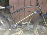
BF034CA0-FBD4-40F5-97FC-1E280E9624B3_1_105_c.jpeg
Bracket attached to frame

When I painted the bottom shelf I masked off a strip in the middle to epoxy the bracket on to.
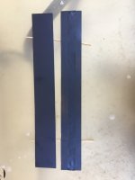
1CB86674-49DA-4E9B-90A2-B815337C7C42_1_105_c.jpeg
Strips painted
The strip on the right has tape down the middle
I placed the short one between the bag and the frame as a rainguard.


I mixed the epoxy and used the finger of a rubber glove to apply the epoxy to the lexan and a little on the bracket. I then placed my motor cable in the bracket. I clamped the shelf to the bracket with c-clamps and let it completely cure.
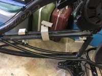
49F9E147-A15D-465D-92EC-0AA6112D9E7E_1_105_c.jpeg
C-clamps

Once cured I sanded and painted the bottom of the shelf, careful to cover any areas for over spray.
 
I found conflicting information about how to use this. I knew I needed to use it because it was recommended by many builders I researched and even recommended by Grin when I made an order inquiry. The problem I had was none of the builds or videos I researched showed how to apply and why it works. In my research I learned that the grease is an insulator so I couldn't understand how putting it on connectors improved things.

After much research I came across this paper Dielectric Grease vs Conductive Grease which explained things to my satisfaction. All was clear to me when the author said this "All greases work by the low viscosity allowing the grease to completely push out of areas with metal-to-metal contact". Once I understood the insulating properties of the grease was pushed out of the way by metal to metal contact I immediately saw it's benefits. Until I understood this I thought, as others had in my research, that the grease had to be applied carefully around the outside edge of the connectors so as not to get any on the pins.

The way I apply it is to put a small amount on the male end of the connectors. Too much grease and it's harder to push the connectors together and it's messy as it gets squeezed out of the connectors.
 
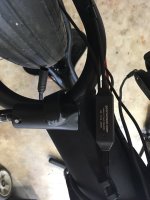
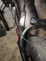
With the bike still on the handlebars I stretched a piece of Silicone Rubber Self Fusing Tape around all of the wires and part of the housing and started spiral wrapping the motor wires coming out of the motor with all of the wires in the wrap. I routed the wires under the bottom bracket. At about the very bottom I separated the power wires from the sensors and motor harness and continued wrapping the power wires up the seat tube stopping before I reached the bullet connectors.
 
Mounting the speed sensor was challenging for two reasons the fat tires meant the spokes were more recessed in the wheel so magnet placement was limited and the cable was too short. I ordered this Speedo Cable Extension to fix the second issue and found I needed to mount the speed sensor on the left side as opposed to the drive train side as I wanted because the magnet was attracted to the derailleur. I used vice grips to attach the magnet as I didn't have a wrench that fit it's weird bolt. I zip tied the sensor to the frame and applied dielectric grease to the male pins on both ends of the extension cable and wrapped the connections with the self fusing tape. I then zip tied everything to the frame.
 
Installing the shift sensor was almost scarier then beating my frame. There are countless videos on how to do this so I won't cover the basics, what I will explain is what I learned in this process. The most important lesson is you need cable cutters that are up to the task. I originally purchased a pair I found at Lowes even thought they said it was rated for aluminum and copper not steel. I figured that since it was a one time use it would be ok. WRONG!

To install the shift sensor you need to cut your shift cable to remove the cap and then cut the cable housing to make room for the sensor. I took out my new cutters and went to cut the cap off. The cable almost cut but instead folded and nicked the cutters. So much for cheap tools. I scoured my brother-in-law's garage and found lineman's pliers and tin snips. Pliers didn't help but the snips got through the last strands. Thinking that I had something strong enough to cut the cable I proceeded to use the snips to cut the cable housing. What a joke! I had no idea that the housing was a group of steel wires wrapping around the shift cable in the middle.

Once I learned the nature of the cable I used the rotary tool to cut the cable. As I started to assemble the sensor with the cable I realized I didn't have any of these Brake Cable and Derailleur Cable Tips Caps End Crimp. Once they arrived I was able to thread my slightly frayed wire through the sensor. Pushing the wire through a small piece of housing caused one of the strands to become separated so I cut it and added some nail polish to prevent further fraying.

I had no clue about working with the derailleur so before I removed the cable I marked the wire's position relative to the clamp bolt, I was in second gear. When I went to reinsert the shift cable I used pliers to try and pull the cable back to it's marks and tighten the cable clamp. I managed to do this but it frayed the ends of the wires so I couldn't put a cap back on.

I decided to order a new shift cable since I no longer trusted it and continued with my build so I flipped the bike back on its tires.

892930AD-D15F-4753-8E7C-FFC24539B07F_1_105_c.jpeg
Gear Sensor Installed

78D7787A-147D-4BA1-97B5-1809FD75F748_1_105_c.jpeg
Gear Sensor Wrapped in Silicone Tape
 
To mount the new brake levers and throttle I had to remove the hand grips. My display is an eggrider and it opens up wide enough to put on without removing the grips. Of course removing grips is not easy otherwise they wouldn't be called grips. I turned to youtube again and found a video of this guy using an adjustable wrench wrapped in tape to slam against the grips kind of like a slide hammer. I didn't have enough room to do any slamming but I adapted his approach by placing the wrench against the grips and then hitting the wrench with a rubber mallet. This worked surprisingly well and the rubber mallet only slightly marred the finish on my handlebars LOL;.

Once the controls were all in place I needed to reinstall the hand grips. Well of course this is also difficult but I found an excellent hack. Before installing the grips spray a little hairspray into the grip. This will act as a lubricant while you install them and once they dry the extra hold can't hurt. I'm not sure of the consequence of doing this when it comes time to remove the grips though.

I originally was going to route the motor harness along the top tube with the rear brake line but instead placed the cord inside the shelf. This made a clean look with the harness coming out just at the handlebar stem. I lost count of the number of times I routed and rerouted the wires on the handlebars. My thumb throttle is on the left and the display is on the right.

The plan was to spiral wrap the two wires with the brake cables on one side and then on the shifter side include the shifter cable. This looked good but I had some problems with adjusting the brakes and I was concerned that the extra weight on the cables was affecting performance. After much trial and error I decided to keep the bike components separated from the electrical components. I ended up running the wires along the underside of the handlebars and securing with zip ties. I may clean the look up a bit by wrapping the handlebars with handlebar tape.

42D3C776-A6DB-4ADC-AAD2-EF30E39456C0_1_105_c.jpeg
 
It's a little strange that I saved this for last some people would have hooked everything up to test it but I skipped that step. My reasoning was that everything was brand new and from a reputable dealer and I really didn't want to plug and unplug the connectors multiple times as the pins are small and I don't want to risk bending them unnecessarily. I fully charged the battery the day before.

We left the power wires running up the seat tube so now we need to connect them. My kit came with a battery that has x-90 connectors and had bullet connectors on the motor side and a pigtail x-90 connector with bullet connectors was included in my kit. All I had two do was connect the bullet connectors from the motor to the bullet connectors on the pigtail so I added some dielectric grease on the male side and plugged them in and then wrapped them with self fusing silicone tape and used the rest of the spiral wrap coming from the motor.
 
With everything in place and wired up it was time for the moment of truth. I turned on the battery and then turned on the display and I had power! I lightly touched the throttle and could feel the bike wanting to move so I hopped on and took it for it's first test ride. I've never ridden an ebike or a motorcycle but I did ride my cousin's mini bike. I hit the throttle and away I went. Riding the throttle was fun and it brought back the joy I felt when riding my cousin's mini bike but the real fun was when I tried the pedal assist. That is seriously cool. I haven't developed a riding style yet but I enjoyed trying different combinations of peddle assist levels and gears with throttle thrown in once in a while for good measure. I should note that at this point I hadn't received the speed sensor cable I needed so I had no idea how fast I was going.
 
Once I hooked up the speed sensor I then programmed my eggrider with my wheel circumference (2334). I entered my battery size as well as set a speed limit for Florida of 20mph. Everything appears to be programmed correctly but I will be exploring it's features as I learn more about it. I would really like two things from it, export the data used to make the graphs and monitor temperatures. I would also like to export data from my bluetooth bms too.
 
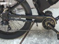
I really wanted to have my chainguard for functionality as well as looks and stealth. I saw a post where a builder with the same bike and motor installed upside down attached the chainguard to his motor. So armed with a few pictures and my newly acquired rotary tool I thought that I might be able to do the same thing. The front attachment for the chainguard was V shaped at the bottom and then went to two points on the chainguard. I cut the V at the bottom and then bent the remaining "straps" to attach it to the motor. I was going to attach it to two screws on the motor with some metal plumbing straps I had. They were too weak but in the process I ended up just using the “straps” on the chainguard and bending them so the top one braced against the motor without attaching it. The front one was bent to allow it to be hose clamped to the downtube. I'm happy with this because it allowed me to do it without welding and would be easily removable without attaching to the motor. I was a little concerned about the motors waterproofness as a result of being unscrewed multiple times.

8B10E07A-D75A-4D3F-8AC2-4FB3FE125588_1_105_c.jpeg
 
I had shifting issues after my build which I at first attributed to the problems I ran into while installing the gear sensor. The first thing I did was replace my frayed cable after researching what kind I needed. I found this one Shifter Cables Set which came with two and they fit but just barely, a little longer would of made me feel better. I also ordered this Cable Cutters even though I ended up not using them. Armed with these and some more youtube searches I was ready to attempt to adjust my derailleur.

I flipped my bike on to my newly acquired workstand, the Handlebar Jack. I wished I had this from the beginning but they were on backorder. I’m so glad I had them for this stage though. Now that I had a display and a throttle I really didn’t want to damage them by resting my bike on them. The jacks mainly let me access the shifter with the bike upside down.

I made the adjustments I learned about by first putting my bike in seventh gear which removes tension from the derailleur. I wish I had known that before I installed my gear sensor. I watched multiple videos on how to remove the cable from my twist shifter and had no difficulties removing the old cable. I took a chance and just left the gear sensor mounted and was hoping the cable would just follow the path of the old one which it did. The cable was just barely long enough to attach to the clamp and put a cap on. I then proceeded to adjust the limit and indexing I learned from youtube. Something was up with first gear. I was able to get it to shift but the derailleur looked too close to the gears. More research revealed what was up.

My bike came with a front chainring of 40 teeth but my BBSHD came with a 46 tooth chainring. Through countless hours of videos and searching I never grasped how this would affect my shifting. Most builds I saw referenced replacing chainrings as related to chainlines and not about teeth. I knew from other builders of my bike that the stock BBSHD chainring would be fine on my bike as far as chainline goes so that's what I ordered. Apparently there is a formula that says 4 teeth = 1 link and 2 teeth = ½ a link so my chain was too short. I had three options, add 1 ½ links to get into first gear, change the gears either front or back or disable shifting into first gear.

I opted to disable first gear with the idea of revisiting this once I understood my riding style and could decide on proper gearing.
 
I built this bike as my primary and currently only vehicle. I’m retired in Florida so my needs for a vehicle are very limited. I took a chance on ebikes even though I never rode one. I rode a bike to work and school when I was in college but gave it up when I moved somewhere with more hills. I remember my hill anxiety and was worried with my unfit old age about range anxiety, I was worried I’d pedal somewhere and struggle to make it home. Of course I’m still going to have range anxiety but it seems more manageable now that it’s a technical issue.

I’m looking forward to the health benefits this bike is going to provide. I didn’t decide on an ebike as an exercise device but it will provide that. Just clown pedaling in the sunshine is going to be way more healthy than sitting in front of a computer or TV all day. I’m also looking forward to the freedom this will provide me. I can pack up my bike for a day at the beach, hop on the bike and ride it to the beach, pull up on the sand where I want to sit and then ride it home when I’m done. No parking fees and no carrying my stuff to and from the beach from wherever I had to park.

Of course this is all of the glamour, I know there will be issues. I haven’t been caught in a thunderstorm, chased by dogs, threatened by cars and trucks (Florida makes this worse I’m afraid) stuck on the side with a flat, sunburned, mosquito bitten and all of the other hazards of cycling.

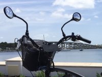
331D8D91-0E3B-464B-9E01-D1006D357FD9_1_105_c.jpeg
Miss Mino'aka
 
This brings me to another thing I did to make me feel better about this somewhat risky decision and that is that I purchased insurance Velosurance for my bike that protects against theft, and damage as well as provides roadside assistance. Everything about this bike is brand new, it’s the closest I’ve ever gotten to a new car. I wouldn’t be able to replace it if something happens so my $2300.00 bike costs me $14.00 a month to insure including roadside assistance. Considering there is no depreciation I think it’s worth it. I can upgrade parts and update my policy to reflect that.
 
This whole process was a blast! I was lucky that I had a garage with a workbench and tools provided by my brother-in-law and help from my friend Jerry. Looking back I can say that I could have done this on my own but all of the tools I would have had to buy just for a one time project would have resulted in a lesser quality build and way more expensive. Aside from the technical issues I imposed on myself with my choice of bike, battery and mounting position A standard mountain bike install with hand tools and the handlebar jacks would have been easy enough.

The other essential element for this whole process is the Internet and all of the resources it makes available. I wasn’t even aware of ebikes until I stumbled on them while searching for ways to carry luggage. A lightbulb went off and I started learning all about them. I posted on forums, read articles, searched google along with Amazon and watched hours of youtube videos. A few resources that stand out are listed below.
 
kauaicycler said:
Until I understood this I thought, as others had in my research, that the grease had to be applied carefully around the outside edge of the connectors so as not to get any on the pins.

The way I apply it is to put a small amount on the male end of the connectors. Too much grease and it's harder to push the connectors together and it's messy as it gets squeezed out of the connectors.
If it helps, the idea behind it is to completely seal out moisture from getting to any of the conductive surfaces or wires or contacts, so essentially "filling up" the connector's airspaces / airgaps is it's job.

If you have "overmolded" connectors like Higo, etc., then just the ends you plug together need it.

If you have "open" connectors like JST, Molex, Tamiya, Anderson, etc., it should go in the entire connector shell so the moisture can't get onto and corrode the crimp or solder area of the contact either, or get into the wire conductors and wick up the wire, corroding it from within.

It doesnt' have to be totally filled...just covering all the conductive surfaces and places water could get in there and sit.

Note that if stuff gets hot, like here in Phoenix AZ in the summer, where it can be 140-160F close to the asphalt in still air (common as there's often no breeze for long periods in the middle of the hot days, as the airflow around the valley begins to change directions between morning and afternoon), the grease will melt and run out of the connectors (at least the open types), leaving only a thin coating on the conductors. This is often still effective, but not always forever, as if it rains and flows warm water (or even hot from puddles on the asphalt splashed onto things) thru the connector, it can wash it away over time enough to allow corrosion to begin.
 
amberwolf said:
kauaicycler said:
Until I understood this I thought, as others had in my research, that the grease had to be applied carefully around the outside edge of the connectors so as not to get any on the pins.

The way I apply it is to put a small amount on the male end of the connectors. Too much grease and it's harder to push the connectors together and it's messy as it gets squeezed out of the connectors.
If it helps, the idea behind it is to completely seal out moisture from getting to any of the conductive surfaces or wires or contacts, so essentially "filling up" the connector's airspaces / airgaps is it's job.

If you have "overmolded" connectors like Higo, etc., then just the ends you plug together need it.

If you have "open" connectors like JST, Molex, Tamiya, Anderson, etc., it should go in the entire connector shell so the moisture can't get onto and corrode the crimp or solder area of the contact either, or get into the wire conductors and wick up the wire, corroding it from within.

It doesnt' have to be totally filled...just covering all the conductive surfaces and places water could get in there and sit.

Note that if stuff gets hot, like here in Phoenix AZ in the summer, where it can be 140-160F close to the asphalt in still air (common as there's often no breeze for long periods in the middle of the hot days, as the airflow around the valley begins to change directions between morning and afternoon), the grease will melt and run out of the connectors (at least the open types), leaving only a thin coating on the conductors. This is often still effective, but not always forever, as if it rains and flows warm water (or even hot from puddles on the asphalt splashed onto things) thru the connector, it can wash it away over time enough to allow corrosion to begin.

Yes that's what I understood from the paper I linked to. With the exception of the bullet connectors to the battery all of my connections are waterproof Higo. Even though these are already waterproof connectors I put the grease on them to prevent oxidation. Apparently the grease also helps prevent tiny scratches by it lubricating nature. I only used a little dab on the male ends.

I didn't realize it would melt like that. The grease I linked to has a temperature rating up to 500 degrees F. All connectors with grease in them are also wrapped in self fusing silicone tape so it shouldn't be able to wash out. Thanks for mentioning this!
 
kauaicycler said:
I didn't realize it would melt like that. The grease I linked to has a temperature rating up to 500 degrees F. All connectors with grease in them are also wrapped in self fusing silicone tape so it shouldn't be able to wash out. Thanks for mentioning this!
I'm sure it depends on the grease you use; the last stuff I used was the stuff you get for car battery terminals. It is "good" for pretty high temperatures...but it begins to flow at fairly low temperatures, relative to what it is probably rated to withstand before it breaks down. I dont' remmeber the ratings on it.

But you can test yours with a hair dryer or heat gun, with a thermal sensor in a dollop of it, and see at what temperature it begins to flow. :) Put the dollop on a metal plate, and heat the plate itself from beneath.
 
Very cool build, I've been contemplating doing one exactly like it. I'm trying to fond a 2018 model Lux 7D with the silver paint color because I think it looks so beautiful. Thanks for posting, your bike looks perfect for lots of relaxing and enjoyable miles.
 
Well done! If you like the hill climbing ability on the stock chainring, this large one will give you the highest top speed on flat ground.

If it sometimes struggles on the steepest grades and you don't mind a slightly lower top speed, a smaller chainring is the best bang for your buck.
 
amberwolf said:
But you can test yours with a hair dryer or heat gun, with a thermal sensor in a dollop of it, and see at what temperature it begins to flow. :) Put the dollop on a metal plate, and heat the plate itself from beneath.

Brilliant! :thumb:
 
Wolfeman said:
Very cool build, I've been contemplating doing one exactly like it. I'm trying to fond a 2018 model Lux 7D with the silver paint color because I think it looks so beautiful. Thanks for posting, your bike looks perfect for lots of relaxing and enjoyable miles.

Thanks! Good luck with your build, you'll find lots of resources to help you with this model. I look forward to many mile of adventures. Barely two weeks into riding it and I managed to get myself in the local paper. https://www.floridatoday.com/pictur...rfront-and-lee-wenner-parks-cocoa/5468977002/
 
Back
Top