Another Bomber/Enduro Clone

BlueSeas

100 W
Joined
Sep 4, 2019
Messages
238
Location
St Petersburg
Not the first person to follow this path. Hope some folks will find my posts helpful.

I found an eBay deal on a Bomber frame for like $250. It inspired me to do my second build. See it here:

https://www.ebay.com/itm/Electric-Bicycle-E-Bike-Frame-Kit-Electric-Bicycle-Bike-Frame-For-Stealth-Bomber/223999637065?hash=item34276b3649:g:V5YAAOSw9htejOax

It's a commonly used frame in China to make cheap knock offs. All steel, very heavy.

Next I purchased a slightly used Zoom fork. On eBay. OK...I know it's not the best, but at under $100 it will get the project started.

I found 17" moped rims, tires and tubes at Treatland.tv, chrome steel rims, moped tires and really thick tubes. Flats will be a thing of the past. The tires are substantial compared to bicycle tires. The rims too. What this stuff isn't, is lightweight.

Highlights on the rest of the build:

1) QS Motor 205 H50 V3 5T
2) Sabvoton 72150 Controller
3) Cycle Analyst V3
4) Headway 40152S 17 Ah cells in a 1P24S 72V pack

I will get some pics and more information posted as the build progresses.

Today, I sat in the garage and laced the front wheel in a 2 cross pattern. The spokes were too short. Went back to my design for the wheel, it was 3 cross. What an idiot! Back to it tomorrow.

Best Bob
 
Ok, you have the frame. There are 2 basic options for a fork. The Zoom 680DH or the DNM USD-8. The Zoom is cheap, the DNM isn't. There are also several forks with prices north of the DNM one. You probably get what you pay for? To get this running, I went with the Zoom. It's a budget build.

Never having attached a fork and headset, I was worried about this. But the frame includes the bearings for a non-tapered 1 1/8" tube fork. Both the forks mentioned fit. Others with tapered shafts might not, or will need different headset bearings. Turns out, there is only one way to assemble the fork to the frame with the pieces on hand.

Will try to capture more pics for the thread as time goes on.
 
Pics or it didn't happen :)

-methods
 
P.S. members will follow links (at times) but I have found the best feedback comes from making your thread "Skimmable".

This is mostly because those skimming. . . are reviewing many, many, many threads. . . so the chance of them taking the time to copy-n-paste key words, search, etc == low.

hence pics (if you want down selection help)

-methods
 
Methods, Thanks for the feedback. Will start including more pictures.

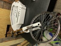
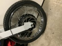
Here is basically the current status. Have the front wheel laced and true. Had to slightly drill the hub for 12G spokes, used #8 washers on the nipples. I think it's going to work out OK after adjustments during the trial period.

5930C170-5166-4DBB-8F27-C55BF7654CA5.jpeg

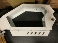
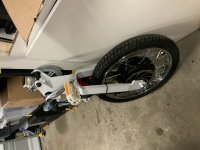
The controller is mounted in the space under the main body of the frame. If you look closely at the next picture, you can see it sandwiched in there. Really kinda big for the space allowed. I'm going to use some weather seal to try and make that space water resistant. Anyone think there needs to be ventilation for heat distribution?

0C825D95-430E-4E27-9C65-098ED38B58BB.jpeg

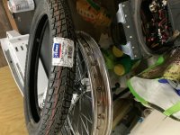
The wheels are 17", here is a picture that includes the tires I'm using. Looked like a reasonable tread for street use, but OK for mild trail riding?

46033D4A-7D8B-4137-A3A6-7431FAFC5B30.jpeg

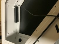
Perhaps somewhat unique, I have parts for a real rear disc brake. However, I'm hoping to use regen alone for rear braking. See the next picture of a cable activated throttle. Not sure this is the final mounting place, but plan to use the usual Wuxing brake lever to pull the cable on this for variable regen. If the Sabvoton controller is as good as the Phaserunner, pretty sure I can get this programmed OK. The only thing you will miss is "feel". There is descent spring tension in this device, but will still be too linear to mimic a normal brake. More later, but the quality is higher than I expected when I ordered it.

72BC2F92-8756-46BB-9413-D6788B8C1FB7.jpeg

For anyone interested, the EBay listing for this is:

https://www.ebay.com/itm/Hall-Effect-Pull-Throttle-3-Wire-Electric-GoKart-Go-Kart-1-4v/191774997198?ssPageName=STRK%3AMEBIDX%3AIT&_trksid=p2057872.m2749.l2649

I think there may be another US based source, let me know and and I can hunt for the link.

Spokes for the hub motor are a week or so away. So I'm going to start on some electrical wiring tomorrow. Initial focus...get the Sabvoton and QS205 to work together, then integrate the Cycle Analyst V3.
 
Before I got to the electrical, the spokes for the rear wheel arrived. Anxious to see if I had the right length, I went ahead and laced the wheel. The spokes are 9 gauge, which just fit the stock QS205 hub.

B4268093-2026-474C-B20C-DCB4EF67D506.jpeg

The swing arm hanging from a rafter in the garage was my truing stand. Learned something new during this exercise. At one point spinning the wheel, the spin acted like it was intermittently catching on something. After not finding anything to cause this, I noticed the phase wires were on the floor near each other. Wonder if they might be the problem. For grins, I held all three phase wires together, and could no longer budge the wheel! It was like it was locked up tight on the hub bearing. Made sure the wires remained separated, and no more spinning problems. There wasn't any power connected to anything. It wouldn't spin because it was acting like a generator, but had no where to send the electrons. Guess I expected that, but not so far as to lock the wheel.

Went ahead and finished the swing arm by installing the crank, crank arms, pedals and checked the chain alignment. The back end now complete pending the rest of the build.

C8D0AF81-9357-43AB-AA94-D98005FF231E.jpeg
 
The BMS arrived, another long lead item, so I went ahead and built the battery pack.

60DF43AA-6BF9-4A2A-B129-7420890075F0.jpeg

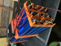
This is a 1P24S 40152S 17Ah Headway build. Made a slight modification to the standard holder system to allow 2 cells to be directly connected in series. Instead of using the 6mm sized hex screws, this connection uses a 6mm set screw with a flat bottom, 16mm in length. Then you simply screw the positive of one cell to the negative of another creating 1P 2S unit. The BMS sense wire on a ring terminal between the cells. Use 12 of these units to make the 72V pack.

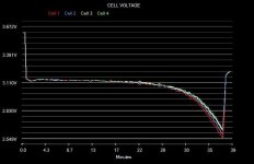
These particular Headway's were sold by the factory as 17Ah, not the usual 15Ah rating. Not sure what they did to raise the capacity rating. Might just cherry pick the cells off the formation testing process. I have 4 more spare cells in testing now configured in a 1P4S configuration. I have run capacity tests at 1C and 1.5C. Here is the graph from my constant rate 24A 1.5C rate test:

7F841F8C-5CDD-4AE0-A527-CFE484F040A1.jpeg

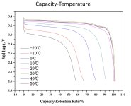
It didn't make 17Ah, more like 15Ah. However the test was run at 15 Celsius, which is lower than standard. Headway provides this guidance in a chart:

F4A85647-C1F0-4F34-9171-695B1DB0D21F.jpeg

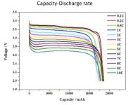
Not getting out the magnifying glass, that looks like it should be 95% of rated capacity, which is only 16.5Ah warranted. That math still shows an expected 15.6 Ah. My testing is still preliminary. I will also run tests at .5C and 2C. Right now waiting for a minimum 20 degree Celsius day, the test setup is in a warehouse. More on this when I finish. Headway has tested up to 10C, and provides these results:

CD381FA7-CBA5-42FE-8C57-06C8B4D121C6.jpeg

I'm not sure I will run full discharge tests at > than 2C, but I will try a couple 30 second tests at around 5C and compare the voltage drops to this table. My actual at 1.5C is close to what's shown here.
 
Some commentary on the BMS. I am a firm believer in using a BMS that reports cell voltage. There is just so much information available for evaluation and diagnosis during the build and after, that the incremental cost is trivial. I can live with a PC connection, but Bluetooth the same cost and preferred.

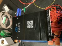
I went with an unknown brand to me, and as far as I can tell, also unknown to the Endless Sphere community. It is a JK BMS Model JK-B1A24S15P from China (where else?) and competes with LLT/XiaoxiangBMS I used in my first build, and Daly, who has just recently been selling a new Bluetooth design.

82FCC375-9C3C-4736-B041-C92405672A15.jpeg

This model is rated at 150A continuous, 300A peak. More than I can get from the battery. Also unique in that it can be configured for operation from 13 thru 24S. MultiChemistry supports all common cell types. It needs a minimum voltage to run, so LFP must be a minimum of 15S.

The other unusual feature is how the balancing works. Unlike many that simply shunt off current to high cells, this BMS actively balances cells, robbing from the rich and giving to the poor. At an advertised rate of up to 1A in this model, 2A on some bigger versions. I'm not sure this is better, but it is different. If this can be perfected, at higher rates, it can mitigate a pack with an under capacity cell by sharing previously unusable energy in higher capacity cells. 1-2A might do a laptop but probably not an EBike. It can work at any voltage, not just when charging.

This is a newish product, and like most, the box arrives without any documentation. The cute QR code pictured on the case links to a very simple website with 4 links in both Chinese and English. Those 4 links go to additional documentation, all in Chinese only. I was able to score an English manual based on a Google search of model number. It's very basic, but sufficient.

So I hooked it up, double checked the connections at the connectors with a multimeter before plugging them into the BMS. At first, nothing. Skimmed manual and rechecked all the wiring, still nothing. Now I'm thinking I have a DOA BMS. So now I go look for a troubleshooting section. Nope not there. Finally I go and RTFM the manual one more time, actually reading every word. I find this: "charger needs to be connected to start the protection board". OK, but WTF? But sho enough, if you follow ALL the directions, it fires right up and instantly connected to my iPad via Bluetooth. Clap if you think this is unusual enough to require BOLDFACE in the manual?

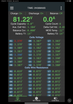
Past these issues, I got the status screen:

4DF05C9B-D928-4A3D-8BC8-376FEF3F1D41.png

Next thing I noticed is it required configuration. It was set to 3.6V cells. Not my 3.2 LFP. Well guess what...it needs a password to change parameters. The "1234" used for the Bluetooth doesn't work, blank doesn't work. So back to trusty Google. I found a post on a different forum to try "123456", well that works. One button changes all the parameters to basic settings for LFP. Customizable if you choose.

Note in my sample screen shot, the high cell is in blue, and the low cell depicted in red. When balance mode is ON, the blue cell blinks, indicating the high cell is moving current to the low red cell. It runs for 3-4 seconds, recalculates and swaps cells if called for. After a couple hours, it had my freshly assembled pack in good balance. However, toward the end, I saw some instances of where the high cell shuttling power to a low cell, suddenly became the low cell, and in the next cycle was on the receiving end. This is called chasing your behind.....I went into the parameters and lowered the balance rate from 1A to 1/2A. This alleviated the problem. This feature is terrific for a new build, and perhaps for periodic use. But at the moment, I'm generally going to leave it OFF. It would tend to mask problems with the pack if any, simply hiding them, by fixing them on the fly.

7C6C1A7E-7B45-4177-B8B2-88AD7EA69AA7.png

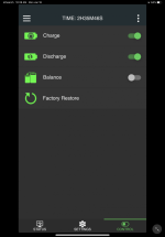
The BMS has a "control" screen, where you can allow or disallow, charge, discharge and balancing. The "discharge" setting might be useful as a security switch. Turn it off while parked. And unless someone has the JK utility app on their phone, it isn't going anywhere fast. No one is going to take off fast pedaling this 100+ lb monster!
 
Thanks for your input on this BMS. I have been looking at it for my next pack build. Please let us know if any more issues arise.
 
I will. It's on the shelf for a few days pending finishing the rest of the build.

What do you think about needing a charger to activate?

The BMS has an on/off wire, basically just B+, about 72V in my case. I would normally wire to the output of my pack circuit breaker, usually turned off for long term storage, but this seems unwise. If that tripped, it turns OFF the BMS. A screw driver gets to the CB to reset, however, the BMS is OFF, AND Power is OFF until you hit it with a charger. I verified this is not a one time, but every time behavior.

In storage, a pack can get depleted by the parasitic load of the BMS, so I guess I will install a standalone micro switch somewhere to turn off the BMS. But I'm definitely not keen on the need for a charger to turn on a good battery in the field. Makes me want to install a BMS bypass. Not sure if it hurts the BMS circuits if you make an external connection manually connecting the BMS input ground to the BMS output ground. Anyone think this is a problem?
 
Pedals, it seems to me, are vestigial on a 150lb "ebike" :). But nice work and problem solving.

Clever end to end arrangement on those headway cells. I considered using those for my current project for their simplicity and safety but they're heavy, bulky, and expensive... I have a couple of my vintage motorcycles setup as total loss (no charging system) and just run a 4s1p headway pack. Ignitions only draw 1A, plus about 2.5A for an LED headlight.
 
Barncat said:
Pedals, it seems to me, are vestigial on a 150lb "ebike" :). But nice work and problem solving.

Clever end to end arrangement on those headway cells. I considered using those for my current project for their simplicity and safety but they're heavy, bulky, and expensive... I have a couple of my vintage motorcycles setup as total loss (no charging system) and just run a 4s1p headway pack. Ignitions only draw 1A, plus about 2.5A for an LED headlight.

Headway isn't as expensive as you might think. It was lower cost than building an equal pack with known quality 3.6v 18650 cells, or A123 cylindrical.

But your right on the pedals, those are only to support the eBike classification.
 
In the States you get away with whatever you can :twisted:

The simplicity factor of headway cells is the only reason to use them.
 
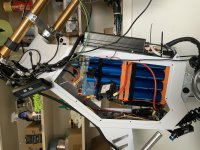
An update on the build progression. The Headway pack barely fit. All the open space you see in the "box" is necessary to get the pack into position. It won't be a remove to recharge pack!

3C894A0A-B70D-4267-A5BD-DB61E26DC1D0.jpeg

I have most of the bits and pieces assembled now into a single unit. And enough wiring to fire up and test the Sabvoton 72150, Cycle Analyst CA3, and QS205 hub motor. It's not yet ready for the road, but getting closer.

f you look carefully, you will see 2 sets of Velcro hold downs for the pack. I'm pretty confident under normal operation and small tumbles, if any, this is sufficient. I could rotate the bike 360 degrees and nothing would go anywhere. However a bigger spill, especially significant jostling upside down, all bets are off. Still considering options here.

That's one reason for the 100A circuit breaker you see dangling, it's to protect from an inadvertent short circuit. Still working on the best place to mount that.

This next picture shows the cable pull throttle for regenerative braking.

FC69CB35-A020-4437-86EE-190B6CA4CA7D.jpeg

This eBrake throttle connects directly to the Sabvoton controller for variable braking regen. The cable is installed, and runs to the usual basic Chinese eBike brake levers. The "pull distance" was just about perfect, not quite getting to the stop point of the pull throttle.

I was able to get regen working and tested without a load, but it will stop the full speed rotation of a steel rim and motorcycle tire is a second or two. However....of note, if you want to disable the throttle a CA3 is required. The Sabvoton with a throttle directly connected, prioritized the throttle signal over the regen braking signal, potentially dangerous. The CA3, due to the eBrake switch, cuts the primary throttle on brake lever activation.

Another thing you might notice in the picture is the orange and clear plastic Wago connectors. I find these really useful in some parts of the build. They clamp and connect from tiny AWG 28 to AWG 12 wire.

4D81E26A-5059-401D-979B-B28DBE384C53.jpeg

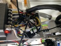
The wiring to the controller. What a messy looking affair. Unless you are willing to cut all the wires, reterminate them to a specific length, or have loads more room to organize, don't know how to avoid this. It works. But not easy to work on. I had this all nailed up after some interface testing with alligator clips, only to discover a bad hall sensor connection and had to unwind it all, fix the problem and start over!

A question or two in the next post.
 
The only thing absolutely not working right is hub motor temperature sensing. The original plan was to have that both in the Sabvoton and in the CA3. Turns out the thermistor on the backup hall cable leads to the same thermistor that's on the primary cable. Can't easily have both devices share a thermistor, due to the way they get implemented.

I never got even close leaving the thermistor connected to the Sabvoton. While it gave me a much more reasonable temp reading "via MQCON", it varied by 50C when the motor was running.

Connected to the CA3, with temperature sensing disabled in the Sabvoton (this required), I got stable temp readings. I only connected the one lead from the hub motor to the CA3, the ground is shared. Adding a second ground wire by alligator clip had no impact. However, even with the CA3 programmed for the usual KTY sensor specs from CA3 guru on this chart, the CA3 read 50+C, when the right answer was about 20C. I manually adjusted the voltage to temp change ratio in the CA3 to get it close. But this is a plug.

The voltage reading at the CA3 is 4.98V with no connection, the reading with the sensor connected about 1.02V. Nothing in KTY line up would indicate 1.02V at 17-20C. Running the motor a bit, increases the temp, as it should. But it's certainly not calibrated. Eventually when I can load up the motor, get some heat generated, I can use an IR gun to see roughly what going on. But am I missing anything? Is this a different sensor, or is the wiring at fault somehow?
 
Finally, an editorial rant. Can anyone in the eBike industry make user friendly software? Both the Sabvoton and CA3 have issues on modern PC machines. Neither display ordinary scalable windows. The Sabvoton is a kludge with many different distributions. Exactly one version, and no others I found, can set up the controller for variable regen. The Sabvoton Bluetooth app is better, but incomplete. Many options not selectable there. I haven't figured out why yet...but the latest CA3 software distribution version, .15?, will not read or write to the CA3 consistently, bombing on most try's at communications. The previous version, from my prior build, .14?, a year ago works. Both using the same Windows "compatibility" settings, which shouldn't really be required with software released in the last few years.

Rant "Off".
 
A builders note on the CA3 DP vs DPS. Great info on the forum here saved me. The speed sensor wire in the normal 6 pin interface cable of the CA3 is not connected to anything. Instead, the patch on the board is connected only to the external reed switch sensing cable. Opening the case, the wire is still there, I cut and removed the reed sensor cable and patched back the standard 6 pin wire. Worked great!

Specific to the QS205, I planned on using one of the spare hall sensors. Turns out they aren't powered unless using that connection for the controller. So I had to tap into one of the primary hall sensors.
 
Sorry, no pics. I got the build on the road today for a very short test ride.

The frame, even on 17" wheels is taller than I imagined. It felt far more substantial at 40 mph than my MTB conversion. The zoom front fork is crap, but I knew that. The rear suspension better, still under evaluation. Might need bigger springs.

Braking was disappointing. I have a mechanical front disc, and attempting to use regen alone for the rear wheel. Regen on the test maxed at about 10A, not enough. Need to see 30-40A to assess regen only rear braking. I installed the disc, and have the caliper on hand if I need to add this. The front was OK, but not impressive. I guess no surprise, it's a bike braking system for a 30-40lb bike, plus a 180lb rider. Here we have a 230lb rider and a 120lb bike.

Top speed in default mode about 40. In unrestricted mode with field weaking about 42 mph. These from the CA3, still needing final calibration. This OK, it's all I was trying for. Acceleration pretty impressive, at least compared to my MTB. Didn't get the wattage/current readings yet.

First priority, fix the rear braking to be effective. The regen might be solved in the controller programming. Might want the rear disc brake. Will be testing these areas next.
 
BlueSeas said:
Finally, an editorial rant. Can anyone in the eBike industry make user friendly software? Both the Sabvoton and CA3 have issues on modern PC machines. Neither display ordinary scalable windows. The Sabvoton is a kludge with many different distributions. Exactly one version
Agreed. SW from quads / drones ruined me. U use chrome apps that are always updated. Connect flawlessly 99% of the time. You can flash firmware to the ESC’s, “through” the flight controller. Firmwares have nightly builds, half dozen devs etc. 3 billion tunings options, everything you’d expect from an open source firmware / hardware system. VESC 6 is god, but not really 15kw+ optimised yet.

Fun build logs
 
Sometimes progress is slow. As previously mentioned, the first priority for "fixing", was the anemic performance of regeneration as a substitute for the rear braking performance. I knew from "manual" testing, by spinning the wheel in the air, and applying maximum travel of the cable actuated throttle, more braking was available. However, my arrangement of using an ordinary brake cable and brake lever, to pull the linear throttle was only using about 1/2 of the available travel.

So first, I went to the Sabvoton controller configuration to try and make adjustments. While you can program the "regular" throttle voltages to scale acceleration/speed to match the output voltages available, there are no such parameters for the Hall effect or pot sensor used for variable regen. So I went in and tried to increase the regeneration current limits to approximately 2X what I really wanted. It did help some, but before I was satisfied, variable regen stopped working entirely. WTF. No matter how I configured things, even manually back to "standard" levels, variable regen seemed permanently "OFF".

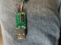
So I did the only thing left I could think of, and reset the controller to factory settings. Then disaster struck. Not thinking that through fully, when I applied power to the throttle on the test stand, the wheel went backwards, and with backwards, so the pedals went flying too, grabbed the USB cable, jerked it out of the PC and the motor controller connection and whipped it around like a slingshot hitting the concrete floor of the garage several times:
D9EED43A-856E-460E-BD09-BB246BBFB464.jpeg

I reconnected the wires, but the unit was dead. Damn. Am I gonna have to wait for a replacement from China? I used the Bluetooth dongle to get the wheel spinning the right direction again (this install is a "1", not the default of "0"). However, as previously mentioned, the USB cable and PC program is required to configure variable regen.

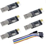
Saved by this forum, a different, historical thread suggested using a USB to TTL driver board that had the same chipset. The link to the eBay part was dead, but I found something similar on Amazon:
2246E978-8FDC-41F4-A253-1222536D17E1.jpeg

$8 for five boards. Would that work? Yep and it's really an improvement. The factory cable connects the USB power from the computer to the Sabvoton, so even if the ignition is OFF, the Sabvoton processor board remains "ON" while the cable is connected. I suppose in a factory, this would be convenient so you could program a controller out of the box with no other connections. But in this setting, testing a build with a 72V battery connected, and iteratively powering the motor, that connection is of dubious value, and if anything, might be a path for frying your computer. I posted the Amazon link on the old thread.

Back to work!

After the reset, variable regen was in fact working once again! Things were looking up. I came to the conclusion I needed more travel on the brake cable that pulls the linear throttle for variable regen. Or I was going to have to kill the brake lever idea, and use a thumb throttle like I did on my first build using a Phaserunner.

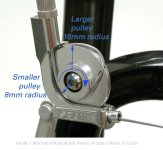
So how do you double the travel distance of the brake cable? The first thing I found was a device called a "travel agent".
1948C582-C6FE-4D30-B5FB-9F46CCA29E5C.jpeg

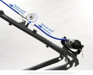
It's designed for V brakes using short travel brake levers. The inline version was discontinued several years ago, but one that mounts to a V brake still around. This device uses two pulleys, one small and the other large to double the travel length of a brake cable. Sounded like just what I needed. Scored a set off eBay, but just didn't have a way to mount it short of completely rebuilding it and welding a mounting bracket. I needed the inline version.
CC64271B-466E-4F1B-A744-21DD9A5F4AFB.jpeg

None available. And for the record, this device designed for turning 5mm pull into 10mm, might be insufficient. I had about 10mm, but needed 20mm. No other device I could find even uses this principle of a double pulley to scale wire or rope travel. There is this one that uses different lever lengths:

99C6018B-9EB5-4B9B-8F2E-93F14E29C37C.jpeg

But that doesn't seem to be the 2:1 ratio needed. I do think this would be easier to build. Some aluminum plate cut to requirements swiveling on a bolt. The in and the out don't have to be in the same place providing flexibility.

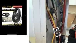
Then I thought of a block and tackle. But in reverse. At first I thought space was an issue, and it would require multiple pulleys. Finally when I realized the linear throttle had more cable that extended with actuation and I found a micro sized pulley I came up with this design (shown close to scale):
10BDAE07-2F84-480F-811F-82F9B9F0B4FD.jpeg

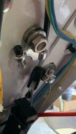
It's almost exactly doubles the pull. Only one pulley, and easy to implement. Off to West Marine, who happened to have these at 2 for $12, a little work on the eBike and I have this pull arrangement now:
2E30A8CB-4DA6-4C0B-BE4F-153C2C984BD8.jpeg

The geometry isn't perfect. Not 100% satisfied yet. However, it works. The brake lever now gets full travel of the actuator, a couple turns on the brake adjustment screw bottoms out the pull length.

A very short test ride before the Super Bowl demonstrated sufficient rear braking. First impression is it's equal to the front brake in effectiveness. Time for a longer test ride to check this out a bit further and to test out some additional Sabvoton parameters. Figure I will get that optimized in pass-thru mode before going on to fine tune the CA3 parameters. This motor does have some kick...during the short test ride I had the front wheel unexpectedly leave the ground on full acceleration from about 5 mph.
 
I guess I need to post an update. Getting pretty close to finishing the build. The second test ride was a partial failure....I managed to trip my 100A circuit breaker about 3 miles from home. While I was able to reset the breaker, the BMS didn't restart. The backup system, the pedals, also failed since my chain tensioner was slightly out of line and kept popping the chain off the freewheel looking for a second speed....that's not there. Maybe I need to carry a few tools? Anyway, my wife rescued me bringing the charger to restart the BMS off the built in inverter on my SUV. (See above, the JK BMS won't wake up without sensing a charge current even when the power lead is reconnected).

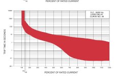
I moved the BMS "power" lead to the source side of the circuit breaker, so the BMS is always powered. However, I wasn't really expecting it to trip with power limiting set at 110A, even though it's only a 100A breaker. As you can see below on the trip curve, I should be able to get 450A for 1 second, or 200A for about 10 seconds. But I was testing slamming the throttle from full off to full on at about 20mph when it tripped. It survived several times, but about the 5th or 6th try tripped it. Either the "transients" are bigger than I think, or the circuit breaker isn't quite up to spec.

414E8224-15B8-4C22-B6DA-66F630876280.jpeg

However, before the meltdown, I collected some statistics on power consumption vs speed. This with battery power limited to 110A, 50A allowable field weakening. The CA3 indicated speed was previously calibrated with GPS at 10/20/30 mph. Florida flat, no significant wind.

10 mph / 3A
27 mph / 12A (60% speed limit on Sabvoton)
39 mph / 33A (top speed, no field weakening)
44 mph / 53A (with field weakening, top speed)

That last 5 mph costs a ton of power....based on the Grin simulator, these are pretty much on target.

https://ebikes.ca/tools/simulator.html?motor=cust_10.38_0.12_0.2_23_0.77_0.0185_0&batt=cust_78_0.3_17&cont=cust_100_250_0.03_V&hp=0&wheel=24i&mass=170&axis=mph&autothrot=true&throt=100

For others with QS 205's, does this look about right?

I have not been able to verify this, but it's supposedly a 5T motor.
 
trazor said:
Subscribed. Enjoyed the BMS presentation. Are you using cable brakes for that e-moto? No way put some shimano zee and other hall lever for regen. Stay away from those Zoom forks, they are just springs without any dampen and dangerous. DNM USD-8 are OK.

That's good advice, the Zoom fork is a POS. In fairness, I bought it used for about $80. It's going to get replaced, probably with the DNM USD-8. Been trying to find one I know for sure won't come with a tapered steerer tube.

I took the Zoom fork apart but couldn't find anything obviously wrong. But I know next to zero about suspension. The main issue I observed is it doesn't spring freely. Its way too hard to compress, and sometimes gets "stuck" partially compressed. It's better after cleaning and lubrication, but still worthless (except for getting the bike on the road).

On the braking, I'm using a mechanical cable operated front brake. Given the 100+ lb bike weight it works pretty well. The ideal brake would use a motorcycle system, but I'm not convinced a hydraulic bike brake would offer much more stopping power. Implementing a motorcycle brake would seem to involve a new front hub for the rotor and something customized to convert the bikes post mount for a motorcycle caliper. But is there even a 20mm axle motorcycle hub with a rotor mount that fits a 110mm fork? More research. Have to look at what SurRons are using.

I have the variable regen working like it should. It shows an initial 30A regen current from a max effort stop at 30mph or above. That's about all, and perhaps a little over what the battery can take. However, it's pretty effective. Subjectively, it slows the bike about like the front disc brake at full effort. Combined, it's reasonably effective. I need more riding miles to determine if it's sufficient. The easiest addition is to install the mechanical brake I already have for the rear.
 
This build is officially on the road! Not probably "done", but are they ever?

First, a couple miscellaneous items:

1) Bench tested on an electronic load for capacity a 4S1P string of the Headway 40152S Cells used in this build at 8.5A, 17A and 25.5A. The cells are rated at 17Ah, charged to 3.65V per cell, discharged to the first cell reaching 2.5V yielded essentially the 17Ah rating.

2) Using variable regen, it takes about a controller limit setting of 150A, to see peak recharge currents on max braking of about 17A. That sets a 1C limit on the charge rate, and I'm hesitant to go any higher. For normal riding, it's sufficient for all stops. Panic stops require the front brake. The CA reports about 8% return, but our bike trails and streets in the city have lots of stops. Flat terrain.

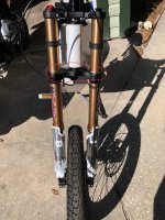
The fork was swapped out with a DNM:

81773D99-62FA-4E70-B9B3-B375AD41E20B.jpeg

E-HP came to the rescue in another thread, reminding me to RTFM when I discovered the extension on each side of the fork isn't exactly the same. It says so right in the manual. There are 2 solutions, preload the long side a little or have the top sections adjusted to match the length. Removing the axle is difficult without eliminating the "preload", lots more things to loosen to remove the wheel, so I went the latter approach.

This DNM fork is a huge improvement over the Zoom, which was basically unusable. I wish there was something in between the $150 Zoom and the $450 DNM, but I guess there isn't anything.
 
Back
Top