
jumpjack
100 W
- Joined
- Apr 11, 2011
- Messages
- 197
They were recently published two interesting documents describing in detail the connections of an "advanced" BMS inside an EV.
"Advanced" because it does not just manage the cells, but the whole vehicle, thanks to several contactors and sensors.
The BMS comes in two variants: modular (BMS-M12, older) and single (BMS-ZD 24, new):
BMS-M12:
http://www.sce.it/wp-content/uploads/2019/04/Manuale-BMS-Modulare-M12.pdf (italian)
BMS-ZD 24:
http://www.sce.it/wp-content/uploads/2019/04/Manuale-BMS-ZD-Lingua-Inglese.pdf (english)
They are used on same vehicle, a Zhidou/Xindayang microcar, so they ar compatible each other, hence one manual can contain useful informations not present in the other one.
The BMS can manage a variable number of cells, from 5 to 24, depending on SW settings and number of BMU modules connected to BCU (for the modular version).
This is my analysis of how the BMS manages operations in the EV:
The key has 2 position: START and RUN.
In START the BMS is powered by the 12V service battery, but the traction battery is still disconnected and the vehicle cannot move; the BMS acts just like a monitor and communicates with the "supervisor" of the vehicle.
When keys is switched to RUN position, the ignition sequence starts: the pre-charge resistor is enabled by contactor K4/KPC; once the capacitors of motor controller are charged after a few seconds, main contactor K1/KM is triggered, enabling the traction battery.
The BMS is powered under two other conditions:
K6 contactor is on (? optional, for customization?)
KCB/KC contactor is on: a charger (EVSE) is connected to the vehicle.
But it is just powered on, it is not enabling the traction battery because the X3 pin is not powered.
It is interesting to note that this BMS does not interrupt the high power line of the traction battery, which is instead externally enabled/disabled by contactor K1/KM.
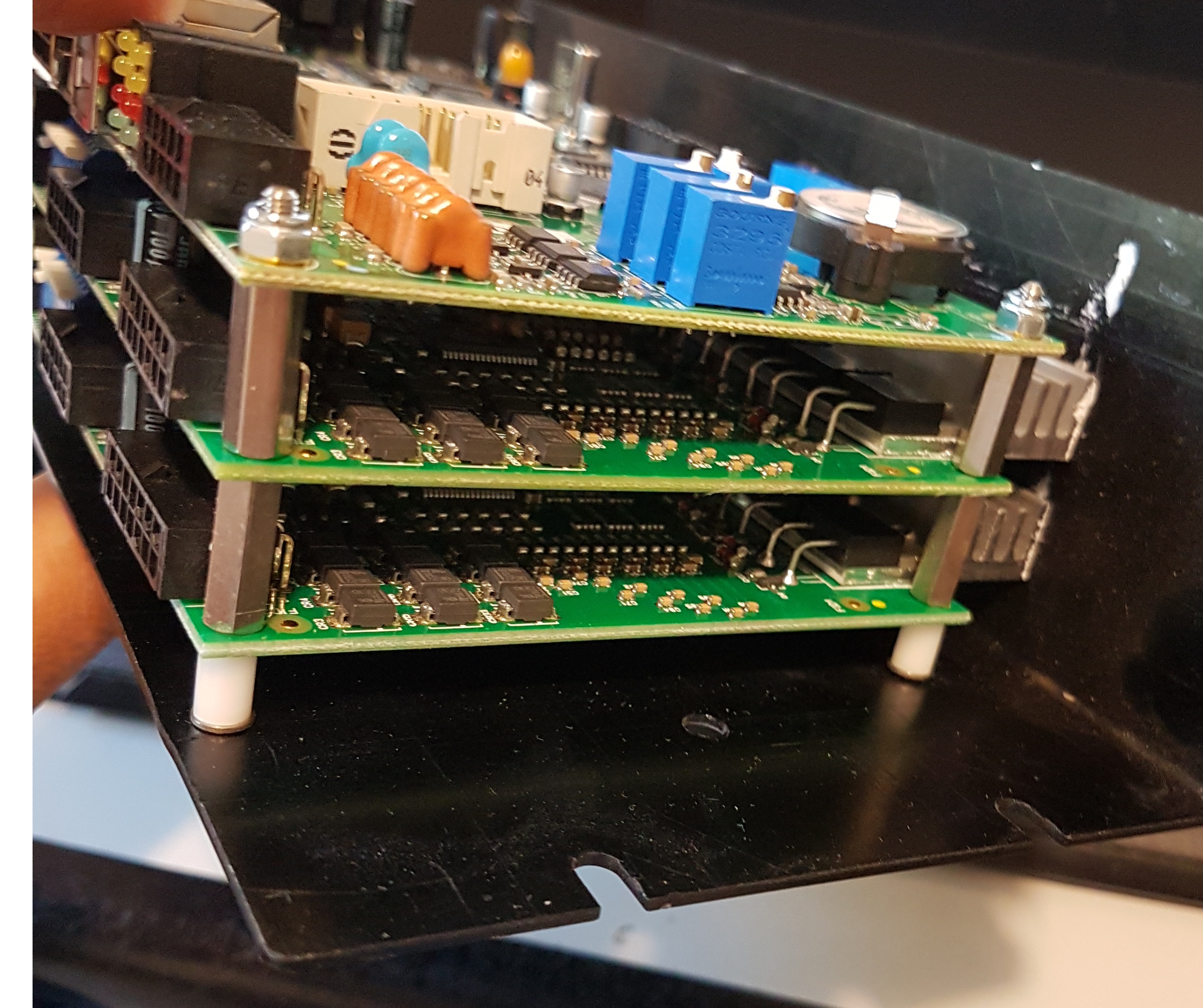
But the BMS contains 24 MOSFETS (they are not visibIe in the document but I took a picture of mine):
The documentation declares 1500 mA balance current for BMS-M12, so probably this is why the MOSFETs are there.
For the BMS-ZD 24 the balance current is just 440 mA and probably implemented just by resistors (I do not have pictures of interior):
Manual of BMS-M12 also talks about an additional external module called "BMU-LK", which is not present in the main schematic on page 7 but detailed in diagram on page 23: it controls K3/KS contactor on the main line of traction battery. It's not very clear to me what else this modules does.
BMS also constantly monitors temperature and voltages of all cells, and it measures current on the main traction line using current sensor LEM DHAB S/18.
All data measured by the BMS are available to the users over ethernet (port 7000), over USB/serial and over CANBUS, but a proprietary SW by S.C.E. named "Terminal Manager" is required to read such data:
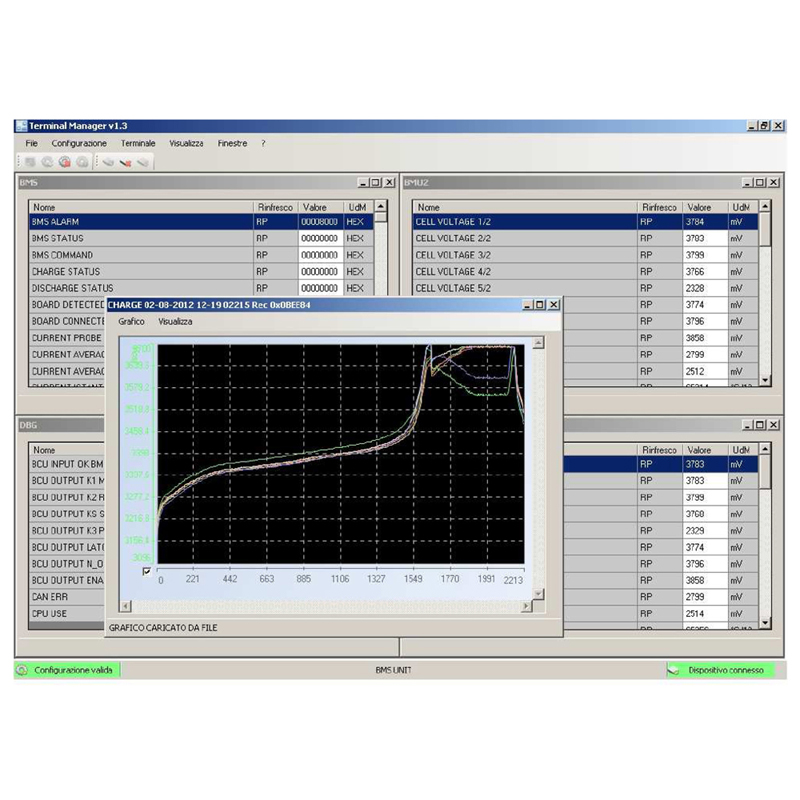
http://www.sce.it/bms-e-batterie-al-litio/software-di-monitoraggio/
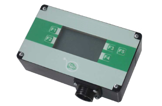
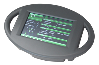
Alternatively, an external monitor/display can be connected to show data:
BMS M12 also mounts a micro-SD card slot to locally log the data, but it is not accessible to final users in the Zhidou/Xindayang vehicle as the BMS is enclosed inside the battery, which cannot be opened unless dismounted from the vehicle, and it weights 150 kg.
The cost of this BMS falls between 1000 and 1500 euros, but it is not clear if it is also sold to single persone besides to EV copanies.
Price of the SW is unknown. Protocol it uses over ethernet, CANBUS and USB is (currently...) unknown.
The Zhidou/Xindayang vehicle also mounts a GSM/GPS unit which in origin was designed to send to a remote server all data read by the BMS; the service is operational for carsharing version of the vehicle (ZD-D1, ZD-D2, ZD-D2S), but not available for single owners, although the GSM/GPS unit is present also in private cars. Here you can find my attempts to decode the network protocol used by the unit to communicate with the original servers. Servers which are still online but no more maintained, so quite broken: they sit on http://main.etheria.it and http://main.eteria.biz (the company/site changed name over years). With demo/demo or greengo/greengo guest/guest or similar couples you can try to log in, but you'll see something is working and something not. My vehicle sent last telemetries in 2014 then it stopped, but I see that there are some logs, on the server, recorded in these days, so something is still working there; I am trying to figure out if I can connect again my car to the site, or if I can locally read the telemetries.
Any help would be appreciated!")
"Advanced" because it does not just manage the cells, but the whole vehicle, thanks to several contactors and sensors.
The BMS comes in two variants: modular (BMS-M12, older) and single (BMS-ZD 24, new):
BMS-M12:
http://www.sce.it/wp-content/uploads/2019/04/Manuale-BMS-Modulare-M12.pdf (italian)
BMS-ZD 24:
http://www.sce.it/wp-content/uploads/2019/04/Manuale-BMS-ZD-Lingua-Inglese.pdf (english)
They are used on same vehicle, a Zhidou/Xindayang microcar, so they ar compatible each other, hence one manual can contain useful informations not present in the other one.
The BMS can manage a variable number of cells, from 5 to 24, depending on SW settings and number of BMU modules connected to BCU (for the modular version).
This is my analysis of how the BMS manages operations in the EV:
The key has 2 position: START and RUN.
In START the BMS is powered by the 12V service battery, but the traction battery is still disconnected and the vehicle cannot move; the BMS acts just like a monitor and communicates with the "supervisor" of the vehicle.
When keys is switched to RUN position, the ignition sequence starts: the pre-charge resistor is enabled by contactor K4/KPC; once the capacitors of motor controller are charged after a few seconds, main contactor K1/KM is triggered, enabling the traction battery.
The BMS is powered under two other conditions:
K6 contactor is on (? optional, for customization?)
KCB/KC contactor is on: a charger (EVSE) is connected to the vehicle.
But it is just powered on, it is not enabling the traction battery because the X3 pin is not powered.
It is interesting to note that this BMS does not interrupt the high power line of the traction battery, which is instead externally enabled/disabled by contactor K1/KM.
But the BMS contains 24 MOSFETS (they are not visibIe in the document but I took a picture of mine):
The documentation declares 1500 mA balance current for BMS-M12, so probably this is why the MOSFETs are there.
For the BMS-ZD 24 the balance current is just 440 mA and probably implemented just by resistors (I do not have pictures of interior):
(page 5)440 mA max @ 4,4 Vdc (10 W resistor)
Manual of BMS-M12 also talks about an additional external module called "BMU-LK", which is not present in the main schematic on page 7 but detailed in diagram on page 23: it controls K3/KS contactor on the main line of traction battery. It's not very clear to me what else this modules does.
BMS also constantly monitors temperature and voltages of all cells, and it measures current on the main traction line using current sensor LEM DHAB S/18.
All data measured by the BMS are available to the users over ethernet (port 7000), over USB/serial and over CANBUS, but a proprietary SW by S.C.E. named "Terminal Manager" is required to read such data:
http://www.sce.it/bms-e-batterie-al-litio/software-di-monitoraggio/
Alternatively, an external monitor/display can be connected to show data:
BMS M12 also mounts a micro-SD card slot to locally log the data, but it is not accessible to final users in the Zhidou/Xindayang vehicle as the BMS is enclosed inside the battery, which cannot be opened unless dismounted from the vehicle, and it weights 150 kg.
The cost of this BMS falls between 1000 and 1500 euros, but it is not clear if it is also sold to single persone besides to EV copanies.
Price of the SW is unknown. Protocol it uses over ethernet, CANBUS and USB is (currently...) unknown.
The Zhidou/Xindayang vehicle also mounts a GSM/GPS unit which in origin was designed to send to a remote server all data read by the BMS; the service is operational for carsharing version of the vehicle (ZD-D1, ZD-D2, ZD-D2S), but not available for single owners, although the GSM/GPS unit is present also in private cars. Here you can find my attempts to decode the network protocol used by the unit to communicate with the original servers. Servers which are still online but no more maintained, so quite broken: they sit on http://main.etheria.it and http://main.eteria.biz (the company/site changed name over years). With demo/demo or greengo/greengo guest/guest or similar couples you can try to log in, but you'll see something is working and something not. My vehicle sent last telemetries in 2014 then it stopped, but I see that there are some logs, on the server, recorded in these days, so something is still working there; I am trying to figure out if I can connect again my car to the site, or if I can locally read the telemetries.
Any help would be appreciated!