48v 1000w controller upgrade (to 60v) again!!!

jimmyhackers

10 kW
Joined
May 11, 2015
Messages
600
heres my controller (ffs people if this post gets moved/amalgamated again im going to be annoyed)


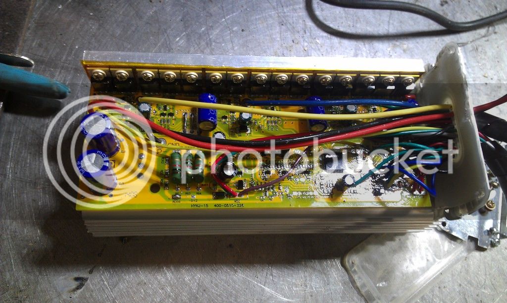
i have an idea of what im doing but i want to double check with people on here.

the blue big caps are all rated at 63v 470 microfarads, and the three smaller ones are rated at 63v 220microfarads.

i figure i just replace these with 100v rated ones at an equal or higher farad capacity?

the mosfets are hy1707, i cant find a datasheet for them :s can someone else point me in the direction? i think they are 75v 80A but im not to sure. either way hopfully i wont need to replace them. is this the case?

and thats my plan...after all that stick 60v into it instead of 48v. is ther anything else i missed??

thanks in advance for the help (and if whoever is goign to move this post again id like to know why)
jim
 
Step 1: Mosfets
I can't see the mosfets dimensions from here, double check if it's to-220 package (google to-220 dimensions). Mosfets of choice are:
1. Infineon n-channel mosfet IPP075N15N3 G V_ds=150V, Rds_on=7.5mOhm
2. Infineon n-channel mosfet IPP041N12N3 G V_ds=120V, Rds_on=4.1mOhm
3. TI csd19536kcs V_ds=100V, Rds_on=2.3 mOhm Note: I blew 100V mosfets on 54.6V so 100V is actually too low voltage for a 60V DC-rail.
file.php


Step 2: Capacitors
Capacitors of choce are:
1. Nichicon PW series 100v, same capacitance as your old ones. This one have longer MTBF than the normal ones. Usually you can't have higher capacitance value because higher voltage capacitors are physically larger for the same rated capacity. You seem to have a alot of space around, but bigger is not always better...
2. Any other 100V you can get your hands on, same capacitance.

Step 3: Resistors
You have to change them too on some units. 433 Ohms is the value for S06S controller and 16s lipo, not sure how your controller works internally.
1. 3W Resistors
 
thanks for the info.

about the caps capacitance...ive been running around 10,000 micro farads worth of 16v capacitors across each of my sla batteries to great effect. the voltage sag (from standstill) isnt as much, its lessened by over 1v per battery. this calculates out in another 20-30mins runtime and a little bit more umph from standstill.

these essentially are doing a better job of what the two larger caps in my controller are upto. so despite your recomendations on that front im still going to higher farads across the battry "in" terminals. from 470microfarad to 1000microfard as they're the biggest i think i can fit in my controller.

as to the three smaller ones. ill probably take your advice. i guess as it one per phase these charge and discharge pretty rapidly and a bigger farad cap might not cope as well. so thanks again for the info.

the mosfets now have me worried. with my sla being a slightly higher voltage than lipos, (really 13.8 - 14.7v) per battery, straight off the charger im close to 56v as it is.... and the controller stays ice cold. adding another 14v or so will bring me upto the 70v mark. im going to have to suck it an see as 15 new mosfets that may not be needed will be a pricey mistake.

the controllers rather close to my gentlemans area so if it gets hot i know somethings happening and to stop :)

now the resistors....by that do you mean the three largish green ones? what are their function and what kindof ohm replacments will i need?
 
Take a look at this about the resistors:
http://endless-sphere.com/forums/viewtopic.php?f=16&t=7361

Nominal Battery Voltage = 24V
LVC = 20 volts
R01(A,B) = bypass
Maximum Safe Operating Voltage = 50 volts

Nominal Battery Voltage = 36V
LVC = 30 volts
R01A = 100 ohm (2W)
R01B = 100 ohm (2W)
Maximum Safe Operating Voltage = 60 volts

Nominal Battery Voltage = 48V
LVC = 40 volts
R01A = 180 ohm (2W)
R01B = 200 ohm (2W)
Maximum Safe Operating Voltage = 70 volts

Nominal Battery Voltage = 60V
LVC = 50 volts
R01A = 200 ohm (2W)
R01B = 330 ohm (2W)
Maximum Safe Operating Voltage = 80 volts

Nominal Battery Voltage = 72V
LVC = 60 volts
R01A = 330 ohm (2W)
R01B = 330 ohm (2W)
Maximum Safe Operating Voltage = 90 volts

Bigger (main) capacitors will introduce more sparking when connecting/disconnecting, use the 100 Ohm precharge resistor when connecting (do not drive with it!). I see no other drawbacks than that.

About the mosfets, some argue that 100V mosfets are enough if the system is well filtered with capacitors. My battery lines are very long, so I'm not a typical user in this case. Maybe 100V is enough, maybe not... Usually I drive mosfets untill they die, then I buy the another ones that are better-with higher V_ds:). Usually they do not explode if they die of voltage spike, they just short. They explode if you pass their current limit. 75V mosfets should die in a matter of minutes at 70V.
 
heres some nice big capacitors inside my controller.


was a ballache but all is good.

went from 63v 470microdfards to 100v 1000microfarads and from 63v 220microfarads to 100v 470microfards.

works on 48v still (could be placebo but maybe a little better than before)....am yet to pump in 60v. im having trouble with finding space for another battery on my bike : s

i may resort to using some smaller rc lipos i have and a relay switch arangment for a "boost" button to add 12ish volts for limited periods.

on a side note here are my battery cap booster packs 4x 16v 4700microfard used in parrallel across each battery.
 
thanks for the interest, the mosfets are hy1707, good luck finding a datasheet. there supposedly rated at 75v and 80A.

havent changed resistors....just the caps.

OMGOMGOMG finally put in another lipo to make 60v. took her for a spin..... 31-2 mph uphill, 37mph on a flat and nearly 40mph downhill. seems marginally more torquey.
for one or two points in my very small test run it was feeling "too fast"

lipo lasted for all of 2minutes as expected, but saying that, it wasnt charged up properly (more like half full). so maybe...4minutes of runtime.

as expected LVC wont work much like the led battery meter(shows full all the time). but i have away round this (read on)

its looking more and more like a 48v to 60v boost button option than a 60v all the time thing.

im going to use a relay to flick between the two modes. meaning i can still go on 48v when the lipos flat, and when im not using the lipo my battery meter will work as normal. i can monitor my lipo voltage with a little meter i have plugged into its balence lead so i dont overedischarge it.

controller and motor were still cool after my little ride......that doesnt say much apart from its not rediculously cooking things.
will report back after my relay mod and a more extensive ride to see whats what
 
did you google the mosfet? there is no picture of your mosfet so there is no way for anyone to help identify it.

60V lifepo4 is a nominal voltage number and represents 20S of lifepo4 which charges to 73V DC at full charge. someone should have explained this already or you should have learned it by now.
 
heres my mosfet


picture isnt great but the only markings on them are HY1707 FS034J12 G. googling hasnt found anything solid like a datasheet. i found a few possible adverts etc with google on chinse websites saying 75v and 80A. if you can find anything else out about them (especially the proper datasheet) let me know please

controller runs 60v fine. ive been using a relay to switch in the lipos i have. no extra heat, just extra speed. each of my 3300mah (30c) lipos last about 3 minutes, but its a fun 3 minutes. after that thanks to the relay arrangment it still runs on the 48v from the SLAs.

heres a crude circuit diagram i knocke dup in paint


the relay is rated at 25a which was a worry and i will get a larger 40amp one for peice of mind. however as i said above its all holding up well. i can switch between 48v and 60v at full throttle with no apparent (touch wood) problems to the relay, controller or motor. i can also feel the torque boost that comes with the 60v

very pleased so far
 
Soon, more people will discover the power of the Volt side. I've always preached for Volts instead of Amps in the noble torque hunt. :D Why not use speed limiter strategically placed at hill speed (low battery) instead of "nitro" switch? This way you can have the same performace all the time?

I've never heard of those mosfets unfortunatly.
 
i could not find data sheet either. came up with a frequency generator.

i would go with 70V for the BVdss from the last 7 in the part number. that is a common labeling scheme for knockoffs from my experience.

don't expect to push more than 10A through them in any case.

you need to get away from the SLA and lipo combination imo. just use a regular 48V lifepo4 or go to 15S of lipo max.

you can buy 5 of the 6S lipo packs and split one of them into two 3S sections and then build a regular battery from them as 15S2P of 5Ah lipoly.
 
thanks for the info.

the "nitro" switch was and always has been a "boyhood dream". ever since i saw mad max and that red toggle pull switch thing on the interceptors gearstick.

i always liked the idea of a big red go faster button, and now i have one :D


welded a pipe to my handlebar to accomodate said switch.

i would go lipo but....im still very reluctant to spend the moolah. i want a minimum of 20ah if i do splash out and im still not entirely set on my end voltage of 60v. what i have so far is great but to take it to the "next level" means an exponential increase in money spent on it.

with oil cooling i really think my motor could go to 96v very happily. meaning what i would really want is two 48v 20ah lipos. then either run them at 48v in parrallel and get 40ah total, and when extra speed is needed they switch to series wiring meaning i get a 96v 20ah battery.

then a brand new controller to cope with it all...maybe Lyen could help but i cant imagine it being below the £200 plus about £350 per 48v 20ah battery so like 900 in total.

with what i have now. the bike was free, the batteries (8x12v 20ah) i got from a charity shop for 30quid, the hub motor kit was 200, and maybe another 30quid in bits n bobs.

£260 so far..... even one new 48v 20ah lipo/life will cost more than my whole bike.

hopefully by the time my current batteries "crap out" lipos will be cheaper
 
Your ideas are contagious! Now I have a "nitro" switch too that turns the 18s 75.6V LiPo battery pack(s) into a 36s 151.2V one. Just don't know yet what to do with it:).

Take a look at Panasonic NCR18650PF batteries, those are very cost effective. Those can be had as cheap as 3-6 €/piece sometimes. 36 cells (100USD if you are lucky) are enough for about 25 km of range. Those are safe cells used in EV:s.
 
glad i could be of service

75 to 150v sounds pretty cool!! whats your switching arrangement?

my idea was using two of the above 5pin type relays to flip between parrallel and series wiring of the batteries. but ive envisaged some problems.

i havnt got round to seeing if a car 12v relay can handle a 48v input signal let alone 48-96v through the switching contactor bit.(because i dont have two 48v batteries :( )

i think with relays id either have to limit the voltage with a resistor to the signal wire. or get a seperate small 12v battery to power them.

as for the 48v-96v through the contactor part :s i think itd be a case of suck it and see. if the contactor arm arc welds itself (happened to me before) itd be a case of finding better relays or disassembly and beefing up the contactor arm

then i wonder about if the relays could handle it all and not need a seperate 12v signal battery. would the 100ma current lost per relay(200ish ma total) on a single battery make a noticable detrimental effect to that battery.

lot of "what-ifs" and"possiblies" there, maybe you can clear some up for me? :)
 
N-channel mosfets as TI csd19536kcs are a bit smaller and easier to hide than the contactors. Use 5V to 12V as a signal to turn them on. There are very good tutorials on youtube on how to use them. Nice idea here :http://www.endless-sphere.com/forums/viewtopic.php?f=7&t=40048&start=50
motorb.gif

Never turn both mosfets on at the same time :D. You can make the mosfets switch by a miniature car relay on the signal side (because car relays are fun and they click so sexy :D). Do not forget to fuse at the strategic places...
 
that seems a very similar way to how ive wired mine. i.e. the booster battery is dead weight when not in use, but becuase of this it can be smaller,as its not used all the time.

ive done a picture (terribly) of my twin relay series to parrallel wiring diagram. for if you have two identical batteries. (sorry if your colourblind)


so lets say each batt is 12v 20Ah (beacuse i dont know what 48-96v does to a relay.....possibly fries it)
when the relays arent energised the batteries are wired in parrallel. output voltage 12v and ah is 40Ah's (doubled)
when the relays are energised the batteries are wired in series. output voltage is now 24v (doubled) and ah is 20Ah's

the main bonus over our current designs would be all the batteries are being used equaly at either voltage all the time. meaning they would drain equally (minus the nominal power required to drive both relays on the one battery)

are you running on 12v to 21v? if your main battery is 12v and your booster is 9v.... it might be easier for you to get second "main" ah sized 12v battery (if your motor can take the full 24v) and do my relay arangement as relays run quite happily on 12v.
 
12V and 9V were values someone sketched in that thread, I'm using two identical 75.6V + 76.6V NCR18650PF packs. I agree that equal packages is the only logical choice. I'm still not clear if I want to use 151.2V in the rain, I will probably just take few multimeter pictures when fully charged and remove the switch again*lol*. The second problem is high rds_on of the 250V mosfets of today. Really 75.6V shuld be enough for everyone, just as 640kb is:). Yes, that drawing is almost identical to your system.

I think that you have to use a bulky contactor, or a tricky mosfet. Contactor is a heavy duty switch whereas the relay is light duty switch. The differences, according to http://control.com/thread/1026206176 :
A Relay:

1. Goes Click when energized.
2. Switches loads of lower wattage
3. Applications include control circuitry
4. Generally switch currents less than 10-15 Amperes.
5. Generally switch voltages less than 240 VAC
6. Switch AC or DC
7. Not normally rated in horsepower.
8. Double throw is typical (normally open and normally closed contacts in one unit).
9. Relay coils are AC or DC, but tend to be 5-24VDC with back emf power diodes to protect relay control electronics.
10. The buck just gets passed here. Relays tend to be "pilot" control devices, controlling more powerful contactors.

A Contactor:

1. Goes Clunk when energized.
2. Switches loads of higher wattage
3. Applications include power circuits (from electric motors to a country's main power grids).
4. Generally switch currents above 10-15 Amperes.
5. Generally switch voltages 120 VAC or greater.
6. Switch AC or DC, resistive or inductive loads, but generally switch AC Loads.
7. Usually includes a horsepower rating.
8. Single throw is the norm (either normally open or normally closed contacts, rarely both).
9. Usually A.C. powered coils (24 VAC for safety- interlocked with EPO or EMO, and Panel open interlock switches; 120-240VAC for simplified operations are typical applications)
10. The buck stops here. Contactors are the real deal. They can be controlled by smaller, less powerful relays.
 
thought id do an update.....

bikes still going strong.

lipo boost batteries......less so.

basically i made a dead cell in one of my lipos and now i have reverted back to using a 7.2ah lead acid battery in their place. still hitting 36 on straight 32ish uphill and 40mph downhill.

was the middle cell that died, other too are fine,, must be something to do with heat build up as middle cell is insulated by the other two.

i think i might do a rant thread about the misleading properties of lipo.

i may try 72v soon, see if i cant blowsomthing else up :)
 
That is probably because of different internal resistance of Lead vs Lipo batteries connected and drained/charged together. My NCR18650PF are still going strong despite "zero voltage" test few months ago, and exceptional abuse (no bms att all, charged to 4.2V sharp, extreme low parallel number of strings (13s2p), discharged over its rated capacity, shorted several times under fuse and fuselink testing and so on)... I think you shall give them a chance, this time used in a clean non-mixed enviroment ;).
 
So, just to check,
I have a CON122 Controller that has these HY1707 FETs as well.
Also 63v caps. If I replace the caps and the resistors I should be fine to run 61.5v?
 
i have just replaced the capacitors and all works well.
you only change resistors if you want to change the (LVC) low votage cutout or the things like the low volatge rail circuit thing for lights.
i havnt done this.

im very close to putting my 3 homemade batteries on the bike. making around 72V.

so we shall see if it can handle 72v :)
 
Back
Top