Cargobike project. Very long john from chromo tubing

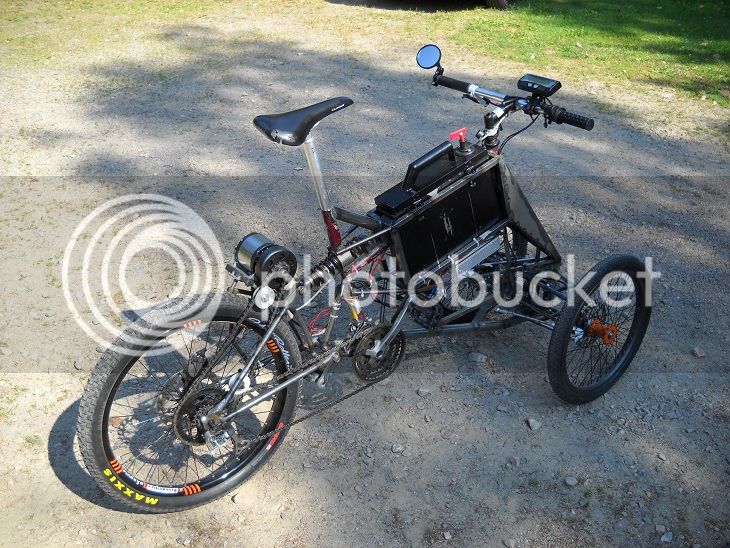
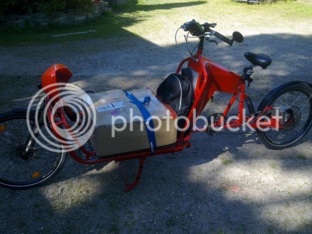
Sorry I forgot to mention in my previous post that the bike looks great. I wish I had the skills to copy a lot of what you did.

One thing I haven't seen mentioned is your terrain. I've never been to Sweden, but it seems like flat roads would be hard to find, or do they follow the topography and are curvy to keep the elevation near constant? Changing elevation is a big hit to wh/km.

If you can get the info for inclusion in Miles' motor comparison spreadsheet for the 120 Pro, then we can determine your optimum gearing. Does your system get speed from the controller or a hall signal, or from a sensor on the wheel? If you can get it without the chain on that would be perfect. The needed info is:
1. No load current at 2 different rpm. If you make one of them the rpm of your typical cruising speed, that will make things event easier to analyse.
2. Actual Kv. I know they say it's 45rpm/volt, but actual is better because it gives you actual torque per amp.
3. Phase-to-phase resistance of the motor. Simply put a low constant current through one phase and out another, and measure the voltage drop. It's too low to measure with a common multimeter. eg My version 1.0 Revolt 120 is 27mOhms. It seems like I remember that they fit more copper on the Pro, so yours may be even lower.

This info is more important for the 120, because the larger stator and thicker laminations make the iron core losses a key component of the analysis, since you're running at so much greater than hubmotor rpm.

John
 
As of now I use the motors signals for speed in the adaptto, so speedreading with just motor spinning is available.

Noload at the 2 different rpms should also be easy to get. Dont have a rpm measure tool, but could easily buy one or figure the rpm from the adaptto.
Do I get the KV just by going full throttle and then divide with the voltage, (with field weakening set to 0) or is it more to it?

How would you suggest the current through a phase measurement? I dont have access to a variable powersource.
Should it be measured from where the controller is connected? Thats also ~1metre of 8gauge wire to the motor, one way.
 
Wheazel said:
As of now I use the motors signals for speed in the adaptto, so speedreading with just motor spinning is available. Noload at the 2 different rpms should also be easy to get. Dont have a rpm measure tool, but could easily buy one or figure the rpm from the adaptto.
Perfect, just use the speed from the Adaptto to calculate rpm, and measure the current. If you do 2 extra no load current measurements with the chain attached, then I think you can get to a breakout of the windage of your wheel from the chain and bearing losses.

Wheazel said:
Do I get the KV just by going full throttle and then divide with the voltage, (with field weakening set to 0) or is it more to it?
Yes, that's it.

Wheazel said:
How would you suggest the current through a phase measurement? I dont have access to a variable powersource. Should it be measured from where the controller is connected? Thats also ~1metre of 8gauge wire to the motor, one way.
I use a battery and a light bulb that's of similar wattage as the battery voltage to get close to an amp of current. If you disconnect your motor from the controller to be safe there's no kind of loop, then you could use your main pack and a 75W lightbulb as the resistor, which will give you a nice stable current. Here are instructions I copied from someone:

"You can measure your motor's DC resistance with a multimeter,
but not directly, because the value will be very low (~0.05 Ohms).
To get sufficient resolution you need to feed about 1 Amp into a
motor winding, while measuring the voltage across it. If the
current is exactly 1A then the resistance equals the voltage. If
the current is not exactly 1A then you can apply Ohm's Law
(Resistance=Volts/Amps).

The tricky bit is, how do you get a known current of about 1 Amp?
You will need a stable power supply (eg. 12V car battery) and a
high power resistor of the correct value (12 Ohms for a 12V supply).
If you can't get an appropriate resistor then you can use a light
bulb (eg. 10~15W auto bulb). To find out how much current the
resistor/bulb draws, connect it to the power supply and in series
with your multimeter set to its 10A range. Record the measured value.
Now switch the multimeter to its lowest voltage range (eg. 200mV)
and connect any two of the motor leads in series with the resistor/bulb.
Measure the voltage across the motor leads. For greatest accuracy the
multimeter probes should be placed directly onto the motor wires or
bullet plugs (otherwise you will also be measuring the resistance of
the connections!).You can measure your motor's DC resistance with a multimeter,
but not directly, because the value will be very low (~0.05 Ohms).
To get sufficient resolution you need to feed about 1 Amp into a
motor winding, while measuring the voltage across it. If the
current is exactly 1A then the resistance equals the voltage. If
the current is not exactly 1A then you can apply Ohm's Law
(Resistance=Volts/Amps).

The tricky bit is, how do you get a known current of about 1 Amp?
You will need a stable power supply (eg. 12V car battery) and a
high power resistor of the correct value (12 Ohms for a 12V supply).
If you can't get an appropriate resistor then you can use a light
bulb (eg. 10~15W auto bulb). To find out how much current the
resistor/bulb draws, connect it to the power supply and in series
with your multimeter set to its 10A range. Record the measured value.
Now switch the multimeter to its lowest voltage range (eg. 200mV)
and connect any two of the motor leads in series with the resistor/bulb.
Measure the voltage across the motor leads. For greatest accuracy the
multimeter probes should be placed directly onto the motor wires or
bullet plugs (otherwise you will also be measuring the resistance of
the connections!)."
 
Wheazel said:
Thank you kindly! I will see what I can come up with. Hard to come by lightbulbs these days, as they are banned, but there will probably be one laying around somewhere.

A low wattage car light and a 12V battery works fine too. I have some 12W 12V LED lamps that I use, but the bulb type doesn't matter. The wattage/working voltage gives you an idea of current. I use a second multimeter set on the 10A current measuring and clip it in line so I can read the current, measure the voltage drop, disconnect and right them both down. I do a second phase-to-phase as a double check.

Do the resistance measurement first, not with an already warmed up motor. If the ambient temp isn't in the around 25°C, make note of the temperature, since temp affects resistance in copper by 0.4% increase for each degree increase in temperature...another reason the guys who allow their motors to run so hot shoot themselves in the foot. Some allow temps that increase resistance by 30-40%, which increases copper losses and reduces efficiency.
 
Did the easy tests until I have sorted the equipment to test phase resistance.

It was hard to get a reading from the adaptto display for current consumption, so I went 5minutes with speedlimit at my regular cruisingspeed. ~41km/h
Consumption 0,28Ah. Should be 0,28*12 for a consumption of ~3,36A

Next I did the wot, but didnt want to go as long and heat up the motor, so I went 2minutes. Consumption 0,20Ah. Should be 0,20*30 for a pretty dead on 6A wot noload.

The display shows ~80km/h at full throttle noload with a batteryvoltage of ~67V (This is also hard to get a good reading from as it tends to jump) and a speedratio of 61,6mm/pole.
Maybe I have to splice the connections and get a multimeter in there aswell for more accurate data. Tried changing the update interval for the screen, but it doesnt seem to filter anything.
I dont get this tho, as I am thinking speed should equal the rpm*ratio, and the rpm should be the speed/ratio.


If I have 1333,33m/min noload speed(80km/h)
61,6mm/pole and 12poles = 739,2mm/revolution
Doesnt get this to add up. This gives 1803 something rpm, indicating a too low kv. (27)

If we instead divide 1333,33 with the ratio 0,0616 we get 21645 electropoles per minute.
But what to do with these other than tie it towards the number of poles to get rpm.
Maybe I am wrong in how the controller counts poles or how many poles the controller see?

Also worth noting is that I had to reduce the Ind timing parameter for the no chain noload test as motor rpm kept pulsing.
Built up, and then lost some rpm. And went on like that, guessing it was a 5second cycle, and the cycle got faster and bigger rpm pulse span with higher ind timing (600-700range).
At value 336 if i recall, it kept calm at a constant rpm. I have had this value close to 600 as the effect isnt there with the small load from the chain and wheel.
Dont know what to draw from this either.
 
It sounds like maybe you are getting to wheel rpm and just need to multiply by the gear reduction to get to motor rpm.

Nice job going for the sonic based measurement, since it looks like that nailed it.
 
Great build looks so sturdy and strong yet has nice lines. Solid craftsmanship bro.

Wheazel said:
Hey, thanks for the inputs! I am actually using turnbuckles for the steering already, but will improve the way I bind the wire to the turnbuckles.
(Right now I have it welded directly to the turnbuckle) This makes me abit hesitant to tense the wire anymore, even if the guidsystem would handle it.
I am getting new turnbuckles tomorrow and will incorporate them with some proper wirelocks.
The reason for the 3mm wire, is to be able to increase tension without damaging the plastic guidewheels.


If you got thinner wires you could jazz up the wires where they meet the guiding system so they don't tear it up. You could possible use parachute chord, or even cable isolator sleeving around the part of the cable that goes around the pulley with max/min turn. Also try using shoot chord itself as steering cable, it might work well as it does not stretch - or so I've been told.

A front fork like this at the angle I have choosen, is not self centering at low speed. It wants to tip to the sides, and there is a small force required to steer from one side to the other and pass the straight position,
since you are basically lifting the front end of the bike slightly.

But it could, at least more or less self centering. You could use steering damper, spring load mechanism or even a gyro over the front wheel that start/stops automatically from take off to whatever speed you find makes the ride stable. Or just make the gyro spin at all time, that should improve stability during speed as well. Even with heavy load of cargo.
 
My bak fiets steering plan is to try the push/pull steering cables for jet skis. One would work since they're sturdy enough for 50mph watercraft, but since pavement is so much harder than liquid water and I'd have human cargo in the box, I'd go with dual cables if only for the peace of mind.
 
John in CR said:
My bak fiets steering plan is to try the push/pull steering cables for jet skis. One would work since they're sturdy enough for 50mph watercraft, but since pavement is so much harder than liquid water and I'd have human cargo in the box, I'd go with dual cables if only for the peace of mind.

Already tested that during this build. It is crap, has too much slack. Probably spent 15hours fiddling/trying with it and then scrapping the idea.
Anything that is trailing, is much more forgiving than something thats leading when it comes to steering. See earlier posts about cablesteering if you are going to attempt it. Will save you troubles. :)
 
Did you try using wires in casings? I'd like to try using brake wires in casings on my velomobile because the tiller will move forward out of the way for entering and exiting the velo. There won't be a lot of curves, or long lengths on mine though. Maybe I should try it.
 
Wheazel said:
Dont know if I get exactly what you mean, but I use hydraulic brakes and I have the gearshift wire for the rear wheel in a wirecasing all the way from the shiftbuttons to the rear shifter.

I mean for the steering. :)
 
Oh stupid me :)
No I did not try to put the wires in casings, other than that I tried to setup the steering with a cased pushpull wire at first.

When routing the wire it was important that the guidewheels were angeled so that the tensionforce affects the wheel as a straight force towards the guidewheel axle.

For clarification.
guidewheels_zps7kliieyo.jpg


But if you use casings, I think it can work aswell if the casings are secured in both ends.
On my tilting trike I just use regular steering rods, but the geometry is shaped so that tilting and the suspension affect the steering to an absolute minimum.
Works good aswell, and I would go for something like that for a velo for sure. Especially since it isnt tilting, which makes life easy.
Just less questionmarks about that.

The front suspension dosent look exactly like that nowadays and the design is improved but you get the idea I think.
3hjuling_zpsmofy0gpz.jpg


Btw the cargobike has now clocked over 300km! :)
 
This value includes ~2meters of 8gauge wire going to the motor (1m each way), and the solderconnections to the phasewires.

According to
http://www.daycounter.com/Calculators/AWG.phtml

1m of 8gauge copper is 0.00206 Ohm or 2,06mOhm.
Maybe this can give a hint? The wires I use are those silicone wires from hobbyking. Very many small threads.
 
Excellent. I went back and looked at my sheet from the day I was measuring resistance of about 20 motors and noticed that I wrote a 9 poorly and calculated resistance as a 4, so my 27 mOhms was incorrect and should have been 29.5 mOhms. Your measurement, minus the extra wire puts your measurement at 29.7 mOhms, so that certainly close enough for me. I use low cost measurement equipment and measured at the 10cm or so phase leads coming out of my still factory fresh V1.0 Revolt 120.

I was hoping the Pro version had more copper, but that's the way rumors go. I'll be sure your measurements are included in Miles next update of the motor spreadsheet. I want to go back and remeasure my HubMonster's resistance to be sure I didn't miscalculate something on it, because I've been using the spreadsheet predictions as a basis for a number of decisions.

My gut feel is that your last reported 26wh/km at 40kph+ means you have it tuned quite well considering your bike has a lot of aero drag. At 1500rpm or so, and the light load for such a powerful motor you are likely to be operating past the point of peak efficiency. I believe that to be a proper tuning for your setup, since often times you will push a bigger load, whether it's a bigger air load going faster, weight in the cargo area, and/or uphill grades. Plus it's more fun to ride with extra capabilities.

I don't think the motor being warm is an indication that something is wrong, since it's directly behind the big wind block of the motor mount and it does make some heat. That's not to say that the Adappto's tuning potential doesn't offer room for improvement, but I don't own one, so I can't help there.
 
The previous ind timing changes seem to have done a small bump in efficiency too. Now its harder to reach over 25Wh/km, and over the past 50-70km or so of riding, it tends to lay around 25, sometimes in the 24s.

Did a comparision with google maps for distance. Turns out my ratio was set at 61,6, when it should have been 64,3. (Changed to 64,4 now) Used a 45km sample.
 
Been busy riding my bike lately, and I like it! So comfortable and practical.
Have clocked 750kms this past month!

Also got maildelivery of an Eaton supply from Allex. Should trivialize charging even more.

Had my first flat. Something punctured through the big bens puncture guard.
VLJ70_zpsozuihir4.jpg


Fetched this package from the dhl office.
VLJ71_zpsjxk7zqfo.jpg


Will be intresting to compare with the numbers I have gotten with the revolt.
I need to find time to fabricate a new swing for the new motor, unsure when I can.
VLJ72_zpssbxtzbc1.jpg


Lately I have been doing some hilly riding and more city and urban environments.
This means alittle lower speed in general and I am happy to see 21-22wh/km even with alot of hills.

For the general contryside commute at ~41-43km/h I see 24-26wh/km depending on wind etc.

Also started a cargobox that covers approx half the cargoarea. Big enough for the majority of grocerys etc.
Will be isolated as its made of ground isolation foam, will be epoxy and fiberglass covered on the outside and have a lockable plate top.
Perfect for multi stop errands/shopping.
 
You might wanna check with Artur about that thin alu sandwich they uses for the Vector battey box. As this material is strong enough to make such a box with vinkeljern in the corners and it is very light weight thin. Meaning you could have a nice cooler on your long john to carry beers and coca cola on those warm summer days, or carry a fresh baked pizza home in the winter time. With the isolation material you will be using the box will be light weight and easy to take on/off the bike as needed. Those alu sandwich panels comes in sheets and are afaik cheap.

If you need rigidity and a strong box you will need to make a frame for the box but if you will use it for cold drinks, grocery etc it should be fine with just them vinkeljern.

That would save you from some dirty fiberglass work. Not to mention you can have them sheets colored to match your bike or maybe a contrast color? Anyway fiberglass i filthy material to work with, turns workshop into mess and the resin stinks and is not good to breathe.
 
Ty for the input. I cant say that I agree about the epoxy tho. Sure it can be messy, and the fumes are not good.
However it is still alot better than polyester resin which really stinks.

I usually just use a gasmask, glasses and long rubbergloves and do the work outside when weather and season permits.
As of now the box is already glued together, with a 6mm plywood layer on the top edges where the hatch will seal against.
The top hatch is almost done and is made of .7mm plate.

I will probably fiberglass it this weekend. Just have to glue in some anchorpoints where I can attach stuff like hinges, lock and fasten the box to the bike.
I am thinking black box, and red hatch. Will see how things turns out :)

Will defenitely have that alu sandwich material in mind for future constructions. I was going back and forth between various materials before I settled on the jackofoam.
Some examples are plexiglass with a steelframe, plywood and plate.
 
Back
Top