ULtra Compact 1800W charger + Eltek programming

wijnand said:
Anyone programmed a FlatPack 2 3kW via CAN?
I have currently 2 FlatPacks 2 2kW in series with an Arduino to control the charge of my Zero motorcycle. This worked for years on a dayly basis perfectly. Now I wanted to upgrade to the 3kW version, but the 3kW version doesn't get the CAN messages completely. Its responding, but it "dips" every second very short in voltage and current. Like it reversed back to the default values or so.
Since I use exactely the same code the behaveour is in the new packs. I tried some timing things but no luck so far yet.
Are your FlatPack 2 3kW supplies the 'HE' (high efficiency) version? Only these can be permanently reprogrammed.
 
Hi everyone

I quit adaptto and am scratching my head to understand how I could replace the adaptto bms and charge "through the motor winding" system. I plan to use one or several flatpack S to charge my batteries (20s 9p + 20s 19p) (so when in parallel 20s 28p).

How would you send 84.2v max to two smart 150A bms ?!

Weight being the absolute priorty as I talk about "always onboard" stuff
 
Hey All.

First off I'd just like to say thank you to Remmie for his great work on these units and for the sharing of his Arduino code. The latter I have enjoyed spending many hours with chopping and changing around to make different displays, such as the OLED's and SPITFT type, work with it, learning some Arduino along the way. My plan is to refine and simplify it as I learn to work better for my needs.
Also thank you to the other users as well, who also put in some great input and helped make it all happen.

I am using these in the RC model sector, as I build custom charge cases and have been looking longingly at the Elteks as a good reliable 48 volt power supply option.
For this purpose I had my electronics wizard design and order me a custom connector board that suits my needs and it is like to show here as I feel others may well like it to for their use also.

We've designed it to work with a small selection of AC input options, there is a 3 pin JST-XH for CanBUS connection and I chose an XT90 for the main DC output. As it's a very capable connector and neat.
If anyone is interested in a board give me a shout, I have 10 so far of which 5 are for me and I can let 5 go. But I will be ordering more as required.

Thanks again.

Ian Contessa
 

Attachments

  • 001.jpeg
    001.jpeg
    160.6 KB · Views: 4,192
  • 002.jpeg
    002.jpeg
    186.8 KB · Views: 4,192
  • 004.jpeg
    004.jpeg
    138.6 KB · Views: 4,192
  • 007.jpg
    007.jpg
    335.2 KB · Views: 4,192
  • 008.jpg
    008.jpg
    295.3 KB · Views: 4,194
  • 010.jpg
    010.jpg
    167.6 KB · Views: 4,193
  • 011.jpg
    011.jpg
    155.5 KB · Views: 4,192
  • 012.jpg
    012.jpg
    232.5 KB · Views: 4,193
  • 014.jpg
    014.jpg
    250.7 KB · Views: 4,193
For those in US, grab 2 while you can:
https://www.ebay.com/itm/ELTEK-FLATPACK-S-48-1800-HE-P-N-241122-125-48V-1800W-RECTIFIER-MODULE-PL-/323224049715
 
Hello All,

Coolice,

I interested for Your pcb connector panel and the frame for Flatpack2 HE.
What's its price and how can we do this business? I've sent You a PM too.
Thanks,
Je@n
 
Coolice,

I interested for Your pcb connector panel and the frame for Flatpack2 HE.
What's its price and how can we do this business? I've sent You a PM too.
Thanks,
Je@n

Hey Buddy.

Sorry mate, I didn't get an email saying there was a reply here.

Great, yes we sure can. I will reply to your PM now.

Cheers.

Ian
 
Hi,

I need some help...
Just bought a FP2 HE as brand new from ebay. I connected the mains 230V only, but no any reaction.
At least the power LED should work, right? Does it need the CAN bus to start-up? I tried to connect but no any traffic, no output voltage.
The fuses are OK, it seems as an unused part, good condition, but I don't see any life-sign.
Should I do somethig special to start it up? The seller can't help...

Thanks
 
Hi !
Usually the units starts up pretty fast.
Unless you have a very new version and they have added something more to the units.
But that would be really strange....

Regards
/Per
 
Hi,

Its Revision is 5.3, SW: 3.00/3.00
If I connect only the 230V mains nothing happens. In this case it looks faulty... :-(
I hoped it has something extra requirement to start-up...

Thanks for reply
 
Hi again,
Well, I opened the FP2 HE (that sold as brand new), and found 2 smd parts damaged behind the fan.
Can anybody tell me what parts are they? Or take me a photo with marking on them?
Thanks in advance...

20180609_120402.jpg
20180609_114022.jpg
 
jean0 said:
Hi again,
Well, I opened the FP2 HE (that sold as brand new), and found 2 smd parts damaged behind the fan.
Can anybody tell me what parts are they? Or take me a photo with marking on them?
Thanks in advance...

20180609_120402.jpg
20180609_114022.jpg

Hey buddy.

They look like transistors to me, smd transistors in this case.

On connecting AC within a couple of seconds you should hear a relay click and the output should ramp up to the default of 53.x volts I found.
No CanBus connection is necessary I've found.

Unless someone's beats me to it, I can open one of mine and photograph them so you can replace with the same type. Assuming we can read the ratings off the top.
Photograph taken but cannot see any markings yet, will look under a magnifier glass next.

Ian

New photo; Managed to remove the pcb coating to reveal the chips numbers.
The big one is; ON RYT 1015A
SMall one; 6CT EE I think is is
 

Attachments

  • 20180609_114957_1528541830810_resized.jpg
    20180609_114957_1528541830810_resized.jpg
    92.7 KB · Views: 3,975
  • 20180609_115052_1528541828880_resized.jpg
    20180609_115052_1528541828880_resized.jpg
    100.5 KB · Views: 3,975
  • 20180609_135856b.jpg
    20180609_135856b.jpg
    89.7 KB · Views: 3,964
Hey Ian,

Thanks for Your effort to take photos to me.
My FP is totally silent, no relay click, no LED lights, nothing.
The PCB and the parts are well enameled, so finding the marks is not easy, .it's true.
Hope, I can get the types of these parts somehow and no others damaged.

Thanks again.
 
Ian, You're great! The bigger is NCP1015 switcher, the smaller is BC817 transistor.
I replace them, hope it will solve my problem...
Thanks a lot, buddy.
 
Hello again.
I still try to program 2 eltek to make an external charger for the Zero DS motorcycle.

I Use this code

Code:
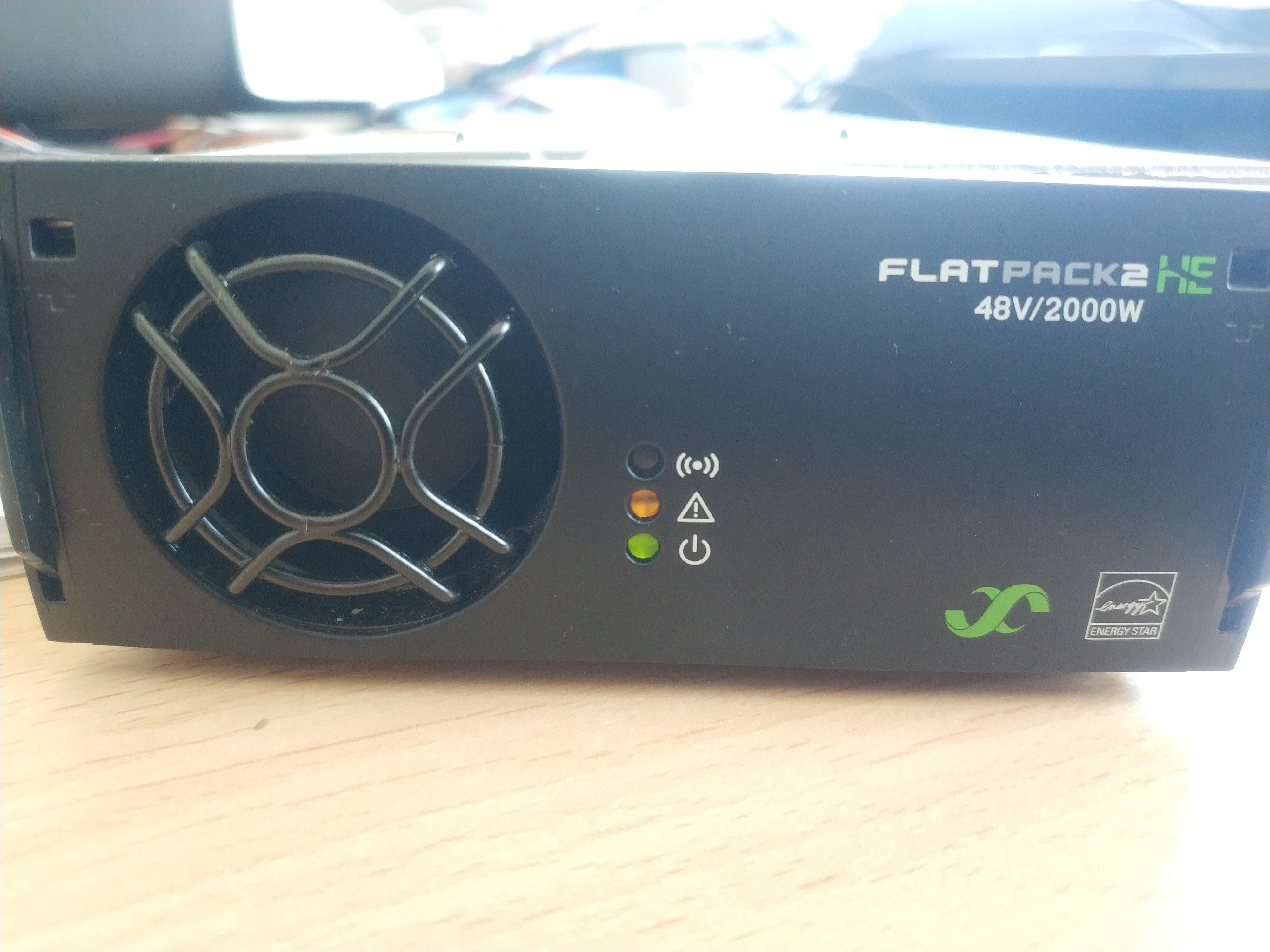
// Eltek Flatpack Permanent Voltage changer, Code By RHO
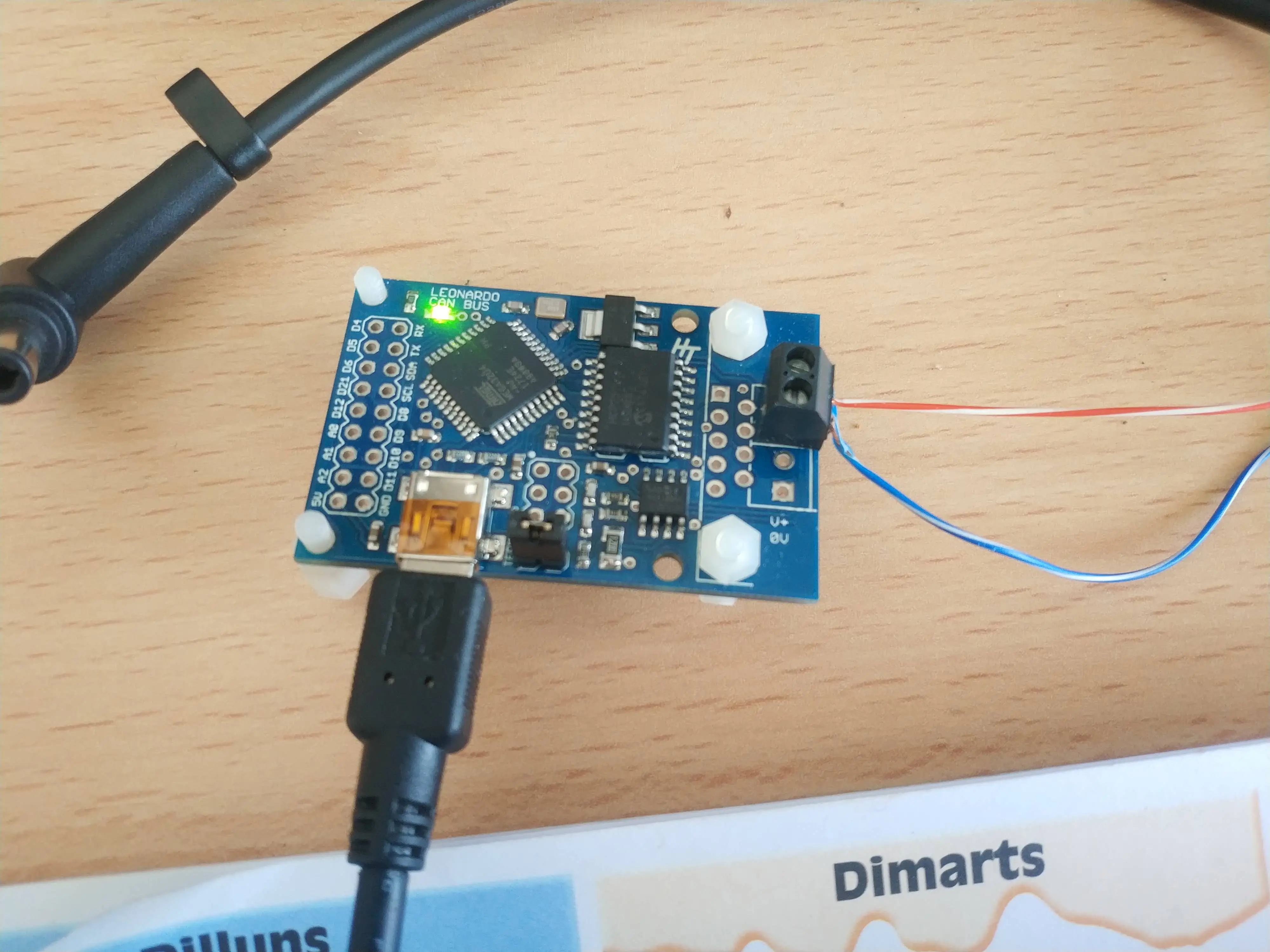
// Used Arduino board is a Leonardo CANbus Board, abtainable at http://www.hobbytronics.co.uk

// The procedure for permanent default voltage change is :
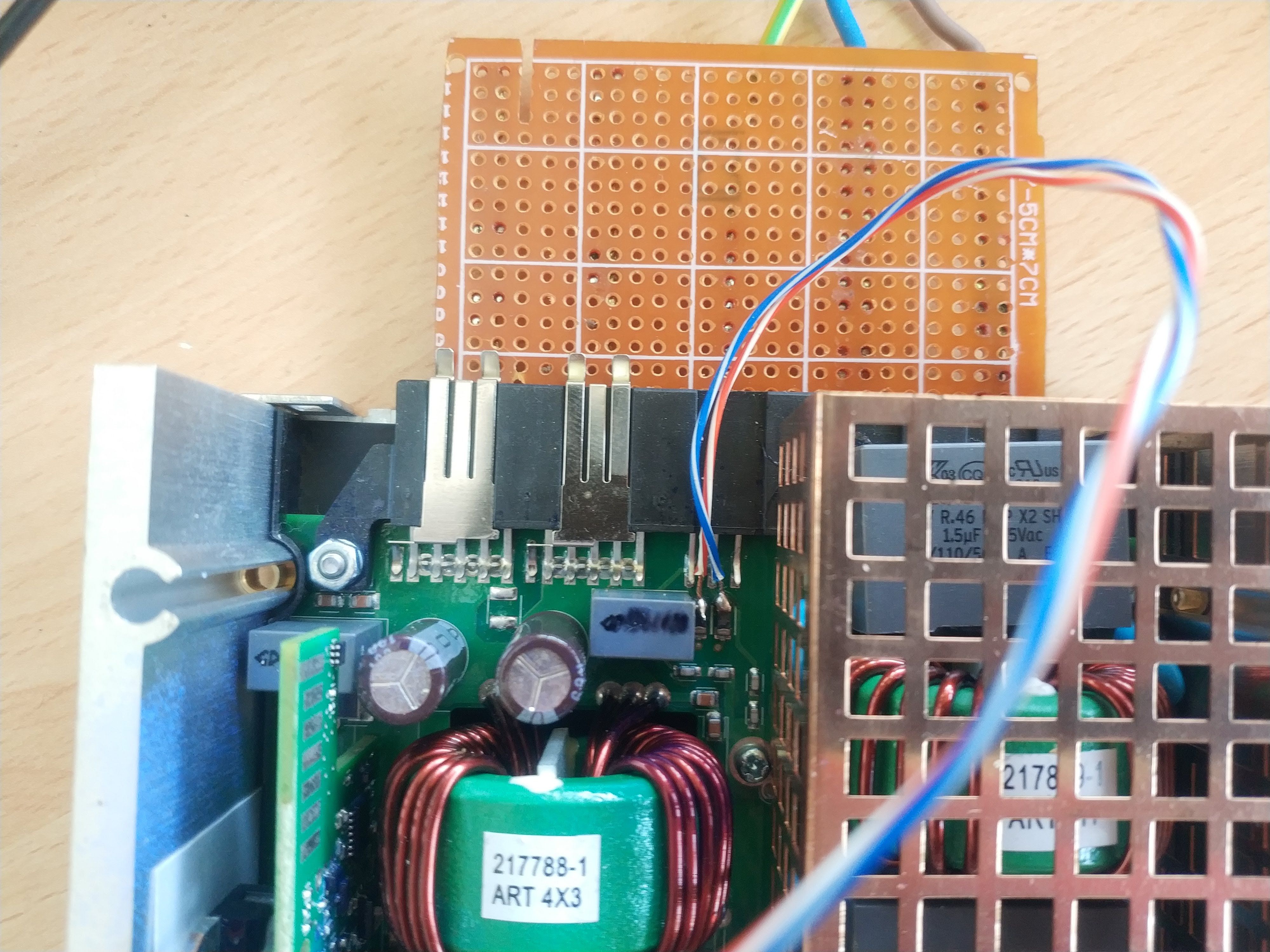
// You have to have a connection to the CAN-bus (obviously)
// if the serial number of your Flatpack is 123456789012
// Change line 46 with the serial nr in the code as below
// send 0x05004804 0x12 0x34 0x56 0x78 0x90 0x12 0x00 0x00 (to log in to the rectifier)
// send 0x05009C02 0x2B 0x15 0x00 0x80 0x16 (to set the permanent default voltage)

// upload code to Arduino
// disconnect Arduino from usb so it powers down
// First power on the Flatpack
// Then power on Arduino via usb

// After about 10 seconds or so the output voltage should change to the new default voltage.
// Now wait 30 seconds and disconnect the power to the rectifier. 

// When you start up again the voltage will default to (in this sketch ) 57.5 Volt. The default voltage is determined by the last 2 bytes of the second command. 
// Multiply your desired voltage with 100 (57.50 => 5750). 
// Convert this number to HEX values (5700 => 0x1680). switch the two bytes (0x1680 => 0x80 0x16) and you have your code for setting the voltage

// NOTE: Some Flatpacks needs to run this procedure several times to change the Voltage. 
// Sometimes the Flatpack shows an yellow led, but no Voltage change. Just repeat the procedure until it changes the voltage.

//CHANGES: LED showing start/end proces

#include <mcp_can.h>
#include <mcp_can_dfs.h>
#include <SPI.h>

const int SPI_CS_PIN = 17;                                                          // Set CS pin to pin 17
MCP_CAN CAN(SPI_CS_PIN);                                                            // Set CS pin for CANBUS shield

void setup()                                                                        // Initialisation routine
{
  pinMode(23, OUTPUT);                                                                // Set pin 9 to output (backlight of the LCD)
  digitalWrite(23, HIGH);                                                            // LED on
  delay(250);
  digitalWrite(23, LOW);

START_INIT:

    if(CAN_OK == CAN.begin(CAN_125KBPS))                                            // init can bus : baudrate = 125k !!
    {
    }
    else
    {
    delay(100);
    goto START_INIT;
    }
    unsigned char login[8] = {0x15, 0x12, 0x72, 0x00, 0x08, 0x46, 0x00, 0x00};     //this is the serial number of the Flatpack + 2 added bytes of 00 each)
    CAN.sendMsgBuf(0x05004804, 1, 8, login);                                       //send message to log in and assign ID=1 (last 04 means ID=1, for ID=2 use 05004808 ) 

    unsigned char setdefaultvolt[5] = {0x2B, 0x15, 0x00, 0x80, 0x16};              //this is the command for setting the default output voltage (Last two bytes, LSB first). 16 80 is the maximum voltage of 57.6 V
    CAN.sendMsgBuf(0x05009C02, 1, 5, setdefaultvolt);                              //send message to set ouput voltage to all Flatpacks connected to the CAN-bus
digitalWrite(23, HIGH); 
}

void loop()                                                                        // main program (LOOP)
{                                                                                  // nothing to do :)
}

/*********************************************************************************************************
  END FILE
  Voltage settings 
  80 16 => 1680 HEX = 57,60 Volt (= highest possible voltage
  E6 14 => 14E6 HEX = 53,50 Volt (= factory set voltage)
  FE 10 => 10FE HEX = 43,50 Volt (= lowest possible voltage)
*********************************************************************************************************/

I get the yellow on but the voltage does not increase to 57.6V.
any advice?
Thank you.

PR3vlp.jpg

1zjnNG.jpg

JK5TUJ.jpg
 
Thank you for answer.
Yep I change the serial number,
If I do not change the serial number, the amber led does not light up
 
Hey buddy.

Just an idea, but I don't see any termination resistors at either end of the CanBus connection and to my knowledge a 120ohm resistor is advised at either end to avoid communication problems.

When I am on my PC I'll see if I can see anything missing in your code as I had fun chopping and changing the posted sketches.

Just zooming in on your photo but are you sure you've connected to the CanH and CanL correctly?
I've not looked past the connector, but the left hand side where you've soldered the blue wire to doesn't look to connect to the pin above it. As the pins track goes off to the left at 45 degrees.

Another idea, this isn't one of those psu''s that needs the ID change;

"Send message to log in and assign ID=1 (last 04 means ID=1, for ID=2 use 05004808 ) "

Ian Contessa
 
Thank you coolice i try to put 120ohm resistor
between can H and can L?
 
Camon said:
Thank you coolice i try to put 120ohm resistor
between can H and can L?

You're welcome buddy.

Yes correct, it just goes over the two Can lines and supposedly helps it to be more stable. Needs one at both ends of the CanBus line.

Ian
 
Thank you again.
So I need to put 220r on the arduino board and the eltek pins?
 
Camon said:
Thank you again.
So I need to put 220r on the arduino board and the eltek pins?

Hey buddy.

Yes correct, solder in a 120ohm resistor across CanH and CanL at either end of the CanBus wire as in the photo;

Arduino-CAN-Bus-Basics.png


Ian
 
I sketched a charger setup. Now I am wondering if CANbuses works as sketched. Do you think the Arduinos are isolated from the canbus using the MCP2515?

The idea here is to have two Arduinos to control current output of the individual Eltek Flatpack2 HE 48's due to the non-isolated canbuses. The switch is used to select low or high output current depending on the fuse of the socket (10A / 16A @ 230V). The OLED is used to display what ever data I want and the SSR is used for switch on/off. It's a shame that the Flatpack doesn't have soft enable pin.

Anyone know any better socket than the IEC320 which I think are rated for 16A? Maybe something weather protected.


charger_scetch1.jpg
 
Hi Janne !

Why don't you first try and just current control one of the units while in series and just see what you get.
The uncontrolled unit should follow the current of the controlled unit by trying to push current but hitting end voltage.

That way you can just get a feel for what works and not.

I wish I had time to do some tests also but I'm fully busy doing a conversion of a car.

Regards
/Per
 
Back
Top