Sensitive throttle vs the sensation of power

speedyebikenoob said:
Oh I see. I was assuming it might have been there because the resistance values in the throttle could change depending on the temperature, and you obviously don't want your bike to run off (although probably very slowly) as soon as you turn the power on.
It could certainly change resistance, but since the controller isn't measuring the complete resistance of the throttle and determining what to do based on that, it won't affect the behavior.

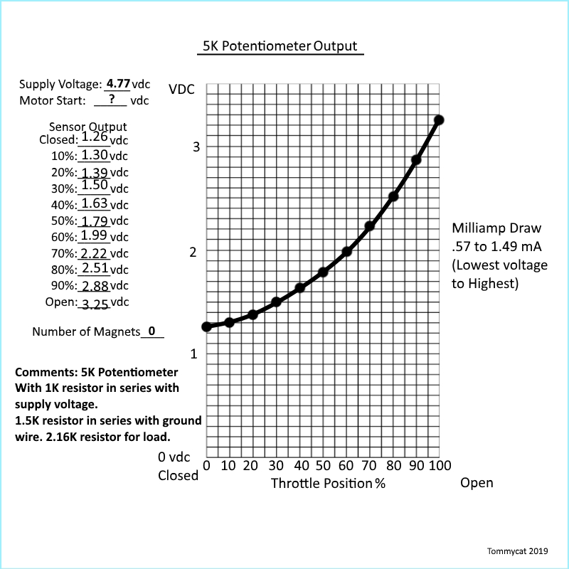
The part of the resistance above the wiper will change at the same rate as taht below the wiper, so the ratio of values between the two remains the same--and that's what the controller is checking (whether it reads resistance, current, or voltage).


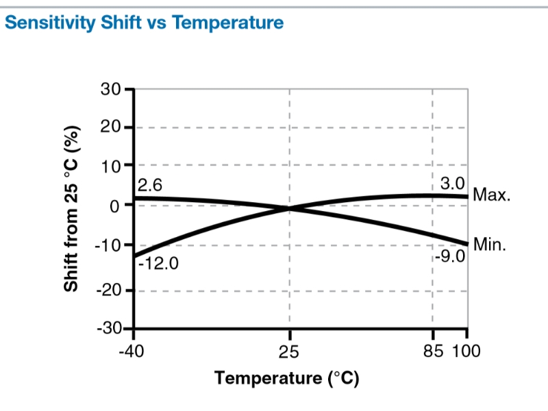
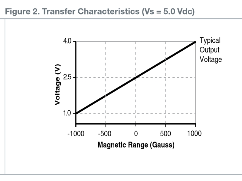
Hall throttles are different, and are not based on resistance...but they also change characteristics with temperature...but also not in a way that would affect the signal coming out.


If they really wanted to make a runaway-failure-proof throttle, it's pretty much this easy:
--two throttles in the same body, mechanically linked to turn at the same time and rate.
--first one is wired normally.
--second one is wired backwards.
--controller (has to be designed for this kind of throttle) checks that each one is changing at the same rate as the other. If it isn't, it stops powering the motor at all, and shuts down with a throttle error. The "hard" part is making the controller do this, because none of the common ebike controllers are designed to. (just some of the expensive OEM types on scooters/motorcycles/cars/etc, AFAICR).
--*however*....you can actually build a fairly simple circuit (analog or computational) that could be installed inside the controller casing of a cheap controller (that couldn't normally support such a throttle) that translates the dual/inverse throttle signal input pair into a single output signal that the controller understands. It coudl even add a simple layer of protection for the controller against shorts in the wiring, water ingress in the throttle, etc., that can cause the controller to fail. (see ZombieSS's Throttle Tamer for an example of a tiny computational throttle translation unit; it does different stuff, but the idea is similar).

That prevents a number of potential runaway issues, including one of the most common: broken ground between throttle and controller, whcih results in basically full throttle voltage on the signal line. Some controllers fault and shutdown when this happens *because* the voltage goes above the high-throttle-limit, but some controllers don't.
 
speedyebikenoob said:
Yes of course! Unfortunately I don't have a wiring diagram, but I can tell you what I did. I'm not at home so I can't confirm which pair but I put a 1.5k ohm resistor between the brown and green wires or the red and blue ones, it was one of those two. I then ran a potentiometer between the black wire on my controller and the black wire on my throttle and turned it until the deadzone was gone. It was a 5k pot.

Thanks Speedy! With your description and this thread...

https://endless-sphere.com/forums/viewtopic.php?f=2&t=26283]

I think I have a handle on it. It's much like modifying a hall sensors output.


Like amberwolf mentions above, some variance in output is experienced with change of temp. So like you say their has to be SOME dead band.

With a SS49E hall sensor as reference both pics...


IeXw7kt.jpg


It's true that a magnet's strength is not linear with distance. But a hall sensor throttle's operation is determined not by proximity, but by changes in the polarity of the gauss. On a single magnet throttle this is easy to see as the distance from the magnet face to the sensor face remains relatively the same. It's the position of the north and south poles in relation to the sensor that causes the change in output voltage. For example, if you where to actually completely remove the magnet from the throttle. You would still see an output of 2.5vdc with a 5vdc input... A bit harder to understand with a two magnet throttle. But as the sensor face moves away from one magnets north pole and towards the other magnet's south pole. I think the gauss would change proportionally much like a potentiometer's resistance does.

Ke32jnC.jpg


But with the poor operation of these controllers (IE: cheap) with hall sensor throttles. It looks like the fault lies with the controllers poorly designed circuitry and design and not the throttles.
I've recently seen where a change of supply power separate from the controllers poorly regulated and weak 5vdc supply can solve this issue of front end dead-band.
Which gets me wondering if the throttle's output is getting dragged down by poor controller circuitry. Or if the low current output
of a hall sensor (~6.5 mA) is not enough to overcome it... at least at the start.
Will be testing this theory. After I profile map Speedy's throttle output...(or a test bench clone :wink: )
 
TommyCat said:
Like amberwolf mentions above, some variance in output is experienced with change of temp.
No, I specifically said the temperature does *not* affect the actual output, because the *ratio* doesn't change. You should reread my post.

The temperature affects teh whole thing at the same time.


And there doesnt' *have* to be any dead band.

It's just done that way becuase it's "easier" to design, and doesnt' require any calibration (or external electronics in a hall sensor unit) to build one that way, so manufacturing is much cheaper.

As you point out, you could move the magnets around in the design of a hall throttle to change the output vs the throttle position...but since every magnet is very slightly different, and every sensor isntall is very slightly different (mechanical variation in placement), every throttle would have to be individually calibrated to get the right voltage range. Plus since a hall sensor output (for those used in throttles) doesn't actually go to zero volts or positive rail, electronics would have to be designed and added to fix this...and those would have to be calibrated as well, if you wanted precision.

The pot throttles could also be designed with no deadband, because the pots themselves don't have one. But it's easier to mechanically design one with a deadband due to where throttle movement/gearing stops vs the pot movement, becuase it doesn't have to be as precise as one that uses the whole range matching the range of the throttle movement.
 
amberwolf said:
No, I specifically said the temperature does *not* affect the actual output, because the *ratio* doesn't change. You should reread my post.

Sorry for the confusion... I was actually referring to a hall sensor. As from it's specs, it shows parameters for temperature errors. And I was under the impression that this would have to be accounted for. But the error levels are so low as to not be a concern.

Here is the 5K potentiometer plot as close as I could get it without having one... :lol:


zT8fCtC.jpg


Even though the 5K multi turn pot I used had consistent 500 ohm average up tics per 10% of turn from one side pin to middle pin.(linear) You can see the nice smooth gradual start-up with the most increases in the later 40%.
Indicating that it would respond much like the O.P.'s experience.
I used resistances as shown to get the voltages in the typical hall sensor voltage zone. Your mileage may vary depending on throttle input controller resistance.
For reference the current draw on the input side varies as indicated.
And with my hall sensor throttle, it also varies on the output side from .77mA closed, to 3.65mA WOT. So re-thinking my low current dead band theory... :roll:
 
TommyCat said:
amberwolf said:
No, I specifically said the temperature does *not* affect the actual output, because the *ratio* doesn't change. You should reread my post.

Sorry for the confusion... I was actually referring to a hall sensor. As from it's specs, it shows parameters for temperature errors. And I was under the impression that this would have to be accounted for. But the error levels are so low as to not be a concern.

Here is the 5K potentiometer plot as close as I could get it without having one... :lol:


zT8fCtC.jpg


Even though the 5K multi turn pot I used had consistent 500 ohm average up tics per 10% of turn from one side pin to middle pin.(linear) You can see the nice smooth gradual start-up with the most increases in the later 40%.
Indicating that it would respond much like the O.P.'s experience.
I used resistances as shown to get the voltages in the typical hall sensor voltage zone. Your mileage may vary depending on throttle input controller resistance.
For reference the current draw on the input side varies as indicated.
And with my hall sensor throttle, it also varies on the output side from .77mA closed, to 3.65mA WOT. So re-thinking my low current dead band theory... :roll:

One thing that I noticed with the graph that is a bit strange is that 100 percent only gives 3.25 v output from the throttle. Don't most motor controllers read up to 4.2 volts or so? So with this set up would you not be getting the maximum power out of the controller even when the throttle is wide open?
 
speedyebikenoob said:
One thing that I noticed with the graph that is a bit strange is that 100 percent only gives 3.25 v output from the throttle. Don't most motor controllers read up to 4.2 volts or so? So with this set up would you not be getting the maximum power out of the controller even when the throttle is wide open?
If a throttle doesn't have a voltage high enough to match the controller's WOT input need, then the controller will only output whatever amount of (speed, torque, etc ***) matches the percentage of input it actually gets from the throttle.

Similarly, if a throttle only goes down in voltage to say, 1.5v, but the throttle expects a 1.38v minimum, then the controller will never go to zero output.


(*** depends on which kind of controller it is, for which of these it does)
 
amberwolf said:
speedyebikenoob said:
One thing that I noticed with the graph that is a bit strange is that 100 percent only gives 3.25 v output from the throttle. Don't most motor controllers read up to 4.2 volts or so? So with this set up would you not be getting the maximum power out of the controller even when the throttle is wide open?
If a throttle doesn't have a voltage high enough to match the controller's WOT input need, then the controller will only output whatever amount of (speed, torque, etc ***) matches the percentage of input it actually gets from the throttle.

Similarly, if a throttle only goes down in voltage to say, 1.5v, but the throttle expects a 1.38v minimum, then the controller will never go to zero output.


(*** depends on which kind of controller it is, for which of these it does)

Okay, yeah I thought as much. Any ways on how I can figure out if I'm getting the most out of the controller? If I were to measure the voltage that the throttle outputs, from which wires would I do it? I just want to make sure I'm not actually losing power by having a less aggressive throttle lol
 
speedyebikenoob said:
TommyCat said:
Here is the 5K potentiometer plot as close as I could get it without having one... :lol:

zT8fCtC.jpg

One thing that I noticed with the graph that is a bit strange is that 100 percent only gives 3.25 v output from the throttle. Don't most motor controllers read up to 4.2 volts or so? So with this set up would you not be getting the maximum power out of the controller even when the throttle is wide open?

You are correct! (controller operation from what I've read is typically between 1 and 4 vdc) As my 5K pot profile was to determine if the next poster below was correct, accuracy of the start and ending points was not a must. Tho I did try to keep it some what in the typical range... Good catch.
My input voltage was a bit low. And not having a controller hooked up, got a bit lazy hitting exact numbers. :wink: So not meant on what resistances to use... ETC.


TommyCat said:
I don't have, or use a pot throttle on which to test. But I would expect both throttles to output voltage in the same relatively linear way.

This cat was wrong... :oops: But this is why we verify right? I can see how the more gradual power curve would be liked.


speedyebikenoob said:
Any ways on how I can figure out if I'm getting the most out of the controller? If I were to measure the voltage that the throttle outputs, from which wires would I do it? I just want to make sure I'm not actually losing power by having a less aggressive throttle lol

From the Magura wiring charts I've seen. You would measure the output voltage by back probing the BROWN wire (wiper/middle terminal) to the BLACK wire. (ground or throttle low)
Then I'd tweak the high side output to at least 4.2vdc or so.
Then do test runs up to WOT. Watching for the point of highest amperage or wattage draw of the motor before it levels out.(making sure it levels out...) If the top dead band is acceptable, good to go. If not recalibrate the throttle to where motor max amp/wattage draw matches throttle voltage output at that time for most usable rotation.
Verifying full wattage readings with motor/battery specs to verify.
 
TommyCat said:
speedyebikenoob said:
Actually I reduced the deadzone to nearly none using resistors and a potentiometer, it still does feel much better than my old hall throttle though, although on first impressions the bike does feel a bit slower. I suspect it's because of the much less aggressive throttle.

If you would be kind enough to post your circuit diagram on how you did this with your potentiometer type throttle, I'm very interested. :thumb: Are you satisfied with the way it acts now? Have you ever taken a milli-amp reading of the output in operation?

Can you expand on what feels slower? Reaction to twist, off the line, build up of speed, top end...ETC.
No ASI controller by chance?


I would love to see it too. I'm seriously thinking to do this mod on my ancheer ebike. Throttle currently only feels like an on-off switch.
 
TommyCat said:
speedyebikenoob said:
Actually I reduced the deadzone to nearly none using resistors and a potentiometer, it still does feel much better than my old hall throttle though, although on first impressions the bike does feel a bit slower. I suspect it's because of the much less aggressive throttle.

If you would be kind enough to post your circuit diagram on how you did this with your potentiometer type throttle, I'm very interested. :thumb: Are you satisfied with the way it acts now? Have you ever taken a milli-amp reading of the output in operation?

Can you expand on what feels slower? Reaction to twist, off the line, build up of speed, top end...ETC.
No ASI controller by chance?


I would love to see the circuit diagram too. I'm seriously thinking to do this mod on my ancheer ebike. Throttle currently only feels like an on-off switch.
 
Matador said:
TommyCat said:
speedyebikenoob said:
Actually I reduced the deadzone to nearly none using resistors and a potentiometer, it still does feel much better than my old hall throttle though, although on first impressions the bike does feel a bit slower. I suspect it's because of the much less aggressive throttle.

If you would be kind enough to post your circuit diagram on how you did this with your potentiometer type throttle, I'm very interested. :thumb: Are you satisfied with the way it acts now? Have you ever taken a milli-amp reading of the output in operation?

Can you expand on what feels slower? Reaction to twist, off the line, build up of speed, top end...ETC.
No ASI controller by chance?


I would love to see it too. I'm seriously thinking to do this mod on my ancheer ebike. Throttle currently only feels like an on-off switch.

Hey, I actually replied to his comment, so if you go back a couple posts you can see what I did, I unfortunately have no circuit diagrams for it though. I'm sure it'll work better for you than it does for me actually because yours is a 250w motor right? It's not an excessive amount, so it should make it a lot smoother.
 
TommyCat said:
speedyebikenoob said:
TommyCat said:
Here is the 5K potentiometer plot as close as I could get it without having one... :lol:

zT8fCtC.jpg

One thing that I noticed with the graph that is a bit strange is that 100 percent only gives 3.25 v output from the throttle. Don't most motor controllers read up to 4.2 volts or so? So with this set up would you not be getting the maximum power out of the controller even when the throttle is wide open?

You are correct! (controller operation from what I've read is typically between 1 and 4 vdc) As my 5K pot profile was to determine if the next poster below was correct, accuracy of the start and ending points was not a must. Tho I did try to keep it some what in the typical range... Good catch.
My input voltage was a bit low. And not having a controller hooked up, got a bit lazy hitting exact numbers. :wink: So not meant on what resistances to use... ETC.


TommyCat said:
I don't have, or use a pot throttle on which to test. But I would expect both throttles to output voltage in the same relatively linear way.

This cat was wrong... :oops: But this is why we verify right? I can see how the more gradual power curve would be liked.


speedyebikenoob said:
Any ways on how I can figure out if I'm getting the most out of the controller? If I were to measure the voltage that the throttle outputs, from which wires would I do it? I just want to make sure I'm not actually losing power by having a less aggressive throttle lol

From the Magura wiring charts I've seen. You would measure the output voltage by back probing the BROWN wire (wiper/middle terminal) to the BLACK wire. (ground or throttle low)
Then I'd tweak the high side output to at least 4.2vdc or so.
Then do test runs up to WOT. Watching for the point of highest amperage or wattage draw of the motor before it levels out.(making sure it levels out...) If the top dead band is acceptable, good to go. If not recalibrate the throttle to where motor max amp/wattage draw matches throttle voltage output at that time for most usable rotation.
Verifying full wattage readings with motor/battery specs to verify.

Ah okay I'll try this. I'm going to go out and get a multimeter tomorrow because my old one died, lol, and I'll measure the throttle and report on what kind of readings I'm getting.
 
Alright so I'm actually getting 4.8 volts from the throttle when it's wide open, which seems pretty high, but the controller doesn't cut out or anything.
 
Back
Top