Revolt RV-series motor review and comparisons

ElectricGod said:
AP 12090
Battery amps: 3.2A
Phase amps: 22A

I'm not looking for an argument here, but as a spectator to this thread it looks like it might help to point out the crux of the problem here:

If 20S li-ion (call it 72V) then controller power in is: 3.2 x 72 = 230W

Controller efficiency is going to be about 95% worst-case, so power out (to motor) would be approx 230x 0.95 = 219W

You said testing was done at WOT, so we can assume 100% duty cycle and Vout = Vin

If total average phase current was 22A, Pout would be 22 x 72 = 1584W i.e. power out was 6.9 times power in.


As true phase current is hard to measure, why not compare battery current/power for the different motors instead? Yes, if the motors are running at different speeds then switching losses in the controller will vary, but we're proably talking about a few per cent error on the final measurement.
 
ElectricGod said:
The AP motor has 3X MORE phase current under no load than the RV-120-regular. That doesn't sound like it's "better" to me. My test was simple. Connect the motor to the controller, crank the throttle to WOT and measure the phase current. I tried all 3 phases on both motors. They were consistent across their phases and always the AP 12090 had 3X more phase current under no load. How is that better?

It is the battery current which is relevant for comparing no-load losses, and not the ripple current in the motor phases (this is what your clamp meter probably was reading).
Even if it features true RMS AC current measurement, it is still might have been designed for measuring it in a range of 50-60Hz, so it's accuracy might be off if the frequency changes. I did look at the manual of your clamp meter and it says 50-60Hz AC current measurement.
As punxor wrote, true RMS phase current is really hard to measure.

ElectricGod said:
1. Outrunners are generally wired delta. I have yet to see one ever wired WYE. I have yet to see an inrunner wired delta.

Only because you never have seen an outrunner wired in star, or an inrunner wired in delta, it doesn't mean that they do not exist.
Most Hubmotors are wired in star btw.

Your signature says it all: It's is a joke, don't take things to seriously, so we should do with your statements which are based on assumptions most of the time and not on facts.
 
I had a play around with a small HK outrunner and a cheap UNI-T UT204 clamp meter. The meter is supposed to have true rms capability.

I tried pwm frequency from 5 to 30khz in foc. At 30khz phase current was 6a. Dropping the switching frequency resulted in higher measured motor current. At 5khz it was over 15a. In trap mode it was about 7a. Controller was a vesc.

Someone suggested earlier in this thread that ripple currents are likely the cause for the high readings. Seems likely as ripple will be a lot higher at low fsw.

EG I'm still a bit baffled why you still believe your measurements when many of us have pointed out they blatantly violate conservation of energy.
 
district9prawn said:
I tried pwm frequency from 5 to 30khz in foc. At 30khz phase current was 6a. Dropping the switching frequency resulted in higher measured motor current. At 5khz it was over 15a. In trap mode it was about 7a. Controller was a vesc.

That makes a lot of sense.
If you would run this motor with 5kHz PWM, the phase current peaks would be always by those 9A higher (6A at 30kHz vs 15A at 5khz).
Or as an example if the current under load would be 100A, it would peak actually at 109A.
The problem is that those additional 9A (or ripple current generally) will just produce more heat in windings and add nothing to the torque output.

I guess you have set it to 30kHz then for this motor, right?
 
ElectricGod said:
Help me understand this: Vout always equals Vin at any RPM or duty cycle. There's no high current voltage regulator or step down circuit in a controller. The mosfets either apply full battery voltage to the phases or they don't. Speed and torque control is not done by adjusting the voltage, but by adjusting the PWM or the frequency of the current sinusoid going to the motor. This is typical Class D amplifier stuff.

Kinda. The inductance of the motor windings plays a part, though. It's smooths out the PWM so motor sees a continuous, lower voltage rather than pulses of full battery voltage. So at 50% PWM the phase voltage is roughly 50% of Vbat. The current flow (and so motor torque) is then limited by ohm's law. That way, with a throttle that only controls the PWM we get speed and (some) torque control.

IIRC it's also the motor inductance that enables the controller to function like a buck converter and so generate phase current that is greater than battery current when phase voltage is lower than battery voltage.

As to why the Alien Power motors seem to have larger peaks in the phase current I can only guess. Maybe it's fairly normal and no big deal, maybe similar peaks exist on the Revolt motors but aren't being tested, maybe it's because there's something nasty about the BEMF of the AP motors. No idea.
 
The discourse about measurement accuracy and precision is fascinating and worthy of a standalone thread with examples/ industry standards. I appreciate EG's effort and those skilled in analysing the real world charcteris of motors, controllers and measurement devices.
 
ElectricGod said:
Phase currents and battery currents as you just saw can be wildly different. I don't think any conservation of energy laws are broken at all. It's just the nature of inductors and iron and magnets interacting that make it "look" like this is the case. Also, there are many examples to be found of real devices that collect the BEMF and reuse it in interesting ways that recovers that energy. The cycling effects of rapidly reversing magnetic fields, collapsing magnetic fields, BEMF, magnets passing by inductors, and other elements create these interesting effects. I agree it is interesting and somewhat mysterious, but there's not magical energy in the phases.

Yes everyone has been trying to tell you that your results imply that there IS magical energy between phases. When you spin your motor at full speed, the voltage between the phase terminals is nearly battery voltage. So if your rms phase current at full speed is 5x higher than battery current, you violate conservation of energy. As Lars mentioned in his previous post you can multiply rms ac currents just like dc to calculate power. Myself, madin, lars and others keep saying this but something isn't clicking.
 
On the weekend of March 17, I deleted quite a few posts (on the last two pages, at the time) that were part of a discussion that devolved into an argument with a sprinkling of personal attacks.

Posts that only discussed motors and electrical phenomena were left intact. Posts that were personal attacks and insults were deleted. I regret that some posts were a mix, and I simply don't have the time or the expertise to determine where I should delete "half a post".

Few people have bought and tested a Revolt motor, so the general public can thank ElectricGod for the pics and info...If anyone disagrees with the results posted here, the accepted remedy is to buy a Revolt motor, and then test it. Then you will have the right to post what your results are.

If there are two Revolt motor threads, please trust that the reading public will determine which thread has the trustworthy information.

For future reference, if anyone here on ES is annoyed by someone, please take the first step of "blocking" them. That way, you won't see what they post.
 
From the looks the stator seems to be on another level in comparison to the previous revolt motors.
Thank you for the pics!
Why they decided to place the hall sensors beside the stator hanging free, and with a large gap to the magnets is kinda strange and also the thing with the large resistors looks unprofessional because they could have put SMD ones directly on the circuit board. I wonder if the magnets are wider as the stator?

Does the bell leak any magnetism (paper clip test)?
Did you do any measurements or no-load tests already?
 
ElectricGod said:
In conversing with Revolt, they won't tell me anything other than what they post on their web site. I think they really dislike me scrutinizing their motors, but won't say anything. You'd think they would want to brag about their motors...at least the Pro and E...nothing. They get annoyed when I tell them what I have found in the motors. They think their motors are perfect or something as is.
I find their attitude just as concerning as the problems you've found in their motors.

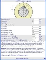
In practice would the single key holding the shaft to the rotor be that big a problem.
 
The stall torque for the Rv100 motors is not known by me but checking the key size vs the material properties for alu 6061 does not show even close to the shear strength limit at 20 Nm:
key shear.JPG

The shear limit is found around 75Nm IF only the key takes torque. The Rv120 motors i've used has an interference fit on axle and bell, enough so i had a hard time with a crowbar to adjust the rotation on the shaft to meet the key slot. This interface will share the load. Is this the case also for RV100?

-->I don't think there will be any problems due to the original key interface if only the key and axle fit is good.
 
Any pictures of failed keyways?

One thing that would help is to glue the connection together with super Loctite or something that will prevent any movement between parts. Its when you get a little free play things start to hammer and you get deformation. Just high power isn't the real problem but shock loading and peak torque.
 
Back
Top