New weldless battery system crowdfunfing project

spinningmagnets said:
If the causal readers take anything away from this discussion, I hope it is the fact that the negative end of an 18650/21700 cell is the connection that is the most sensitive to any heat that is used in the connection process . Conquer the negative end, and the positive is easy.

I haven't found any way yet to DIY ultrasonic wire-bonding.

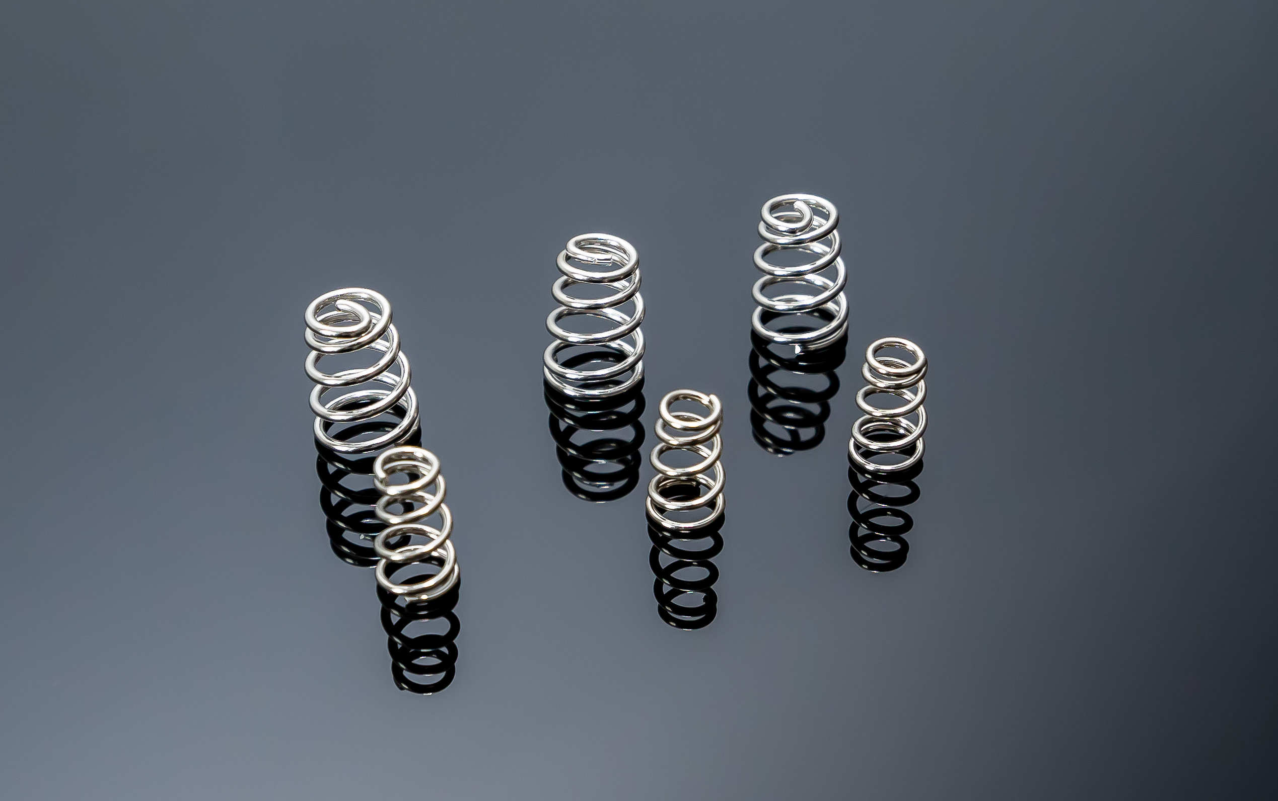
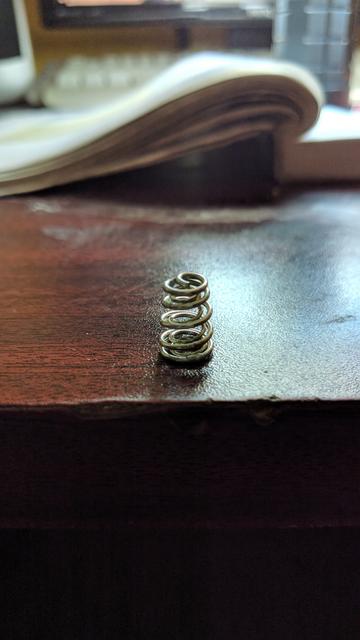
Designs that use a spring on one end seem to insist on using the spring (either coil or leaf) as the conductor. I think there is some potential in having the spring and conductor be two separate elements.

So true that the negative is always the delicate one, and the trick that if you master you've got it all.
Yep, you must separate the spring from the conductor. You also must maintain clamp loads without creeping materials or fatigue to have success. It's a design challenge to keep light and compact but not impossible. :)
 
I'll be sampling a preview version of the engineering animations in about 14 days, it's about 780 megs of 3d files with rotating orbital cameras and transform deconstructions, because i have to illustrate it very professionally to have some robo arms to do the box building at a price that is 15% the price of Tyva. i'll write some PM's at that time.
To be objective it's even necessary to hire an engineer to commission the tooling to micron precision.
I became avid about this project recently because i figured that with only 10k of machines I can provide complete kits of boxes that can be assembled at home in a couple of hours, and with some extra machines the assembly time on delivery goes to 15 minutes. which can be sold for music amplifiers, solar arrays and so forth, and how to integrate advanced chemistry and polymer science and stuff to make it very safe, and how to integrate power user features which provide flexibility and up to 150 amps, the amps are only limited by the friction contacts. that's variable, what do you think the upper limit is? I definitely agree with all the design constrictions that you state.
The tricky thing is that i had to design various robo arms and laminating and other factory elements, i.e. to crowdfund i have had to design every process of a "very wishful" factory. it's all in theory. imaginary. but the technical reasearch is totally referenced and practical and the cash and time that can be saved for electricians and home mechanics and packpackers and party people various power packs is a totally real, bank-logical and achievable at the moment. and i agree totally about the technical preferences. the engineering presentation also has goats on motorbikes and a ferrari modified rickshaw and some aliens from space that appear later in the video:) it's best if i sound like a crazy dreamer at this stage with some designs that you have had previously.
 
So, would you like to have some help for the spring contacts?
I've gathered quite a bit of experience regarding very high current springs, and I can put in a hand if you want.
 
If you are worried about the springs vibrating loose, reduce them by half. Cut some of the plastic sleeve off the negative end of the battery and build a clamping / grounding system (easily 3d printed or machine milled) that clamps the end of the cell in metal so that the cell doesn't bounce around in between two springs and it is grounded. The you can use a spring system on the positive end, or a bolt system what ever you feel is best.

:D :bolt:
 
spinningmagnets said:
...... the negative end of an 18650/21700 cell is the connection that is the most sensitive to any heat that is used in the connection process . .

I haven't found any way yet to DIY ultrasonic wire-bonding.
But even ultrasonic bonding has to generate sufficient heat to fuse the joint. !
Some cell manufacturers give specific detailed instructions on where to locate the weld spots on the base of the 18650 cans. Basicly, avoid the center 5mm area !
 
Hillhater said:
But even ultrasonic bonding has to generate sufficient heat to fuse the joint. !
Some cell manufacturers give specific detailed instructions on where to locate the weld spots on the base of the 18650 cans. Basicly, avoid the center 5mm area !

or just use the top ring. :wink:
 
liveforphysics said:
flippy said:
vruzend is a flawed concept with no regard for safety. that is simply the end of the story.

anything less then spotwelding is a compromise in safety and reliabliity.

That's almost right, except that I've not yet seen a spot welded pack that was a good example of safety or reliability.

>99% of the solderless battery pack designs suck. >99% of the spotwelded packs suck. 100% of soldered packs suck.

That doesn't mean he couldn't jump into the 1% of good solderless pack designs, but it's non-trivial to design. I would personally throw away spot welded or soldered cylinderical cell packs if I had them laying around, because I've cut open hundreds of 18650 cell bottoms to measure the melted/retracted seperator edge that touches the can floor. If you're spot welding or soldering, your cells are damaged by that process. This means you could get lucky and have a type of damage that doesn't show up as catastrophic failure long term, but it's no guarantee of such luck.

Heat process to bottom of cell = fail IMHO

Luke I'm curious... So how do you wire up you cells ? Ultrasonic welding ??? If so, you have some seriously expensive equipement. I wish 18650 were made with small threaded posts like mini version of headway cells... With silver plated copper threads and plates...
 
flippy said:
Hillhater said:
But even ultrasonic bonding has to generate sufficient heat to fuse the joint. !
Some cell manufacturers give specific detailed instructions on where to locate the weld spots on the base of the 18650 cans. Basicly, avoid the center 5mm area !

or just use the top ring. :wink:
Whilst that avoids any issues with the base of the cell, it introduces the possibility of heat damage to the insulation inside the top ring and hence shorting the cell. ! :shock:
 
You need different fixtures. It is being used in the model 3 for example.
 
No doubt....and that precision robotic ultrasonic welder !
But previously they welded to the base of the cell also and now they produce their own cells (21700) which may have a heat resistant top insulator ring if they felt it necessary.
 
the top ring is much denser and relativly far away from the PTC, so i dont see major issues with that. if there was a fixturing method that does not include having a factory the size of a small village i would use that.
 
flippy said:
the top ring is much denser and relativly far away from the PTC, so i dont see major issues with that..
Its not the PTC that is of concern.
It is the -ve can rim that you are welding to, being only separated from the +ve top cap by a thin insulating ring insert. Excess heat on that weld and you dead short the cap to the can.
 
i know, but i have done tests with bare cells from a tesla pack and i could use massive amounts of power and almost penetrating a .3 strip before the edge gets damaged enough to get even close to the + rim. the power levels were much higher then what a regular bottom weld coud handle. it would penetrate every time and sometimes cause the cell to go thermal (no fire) when i tried the same power level on the bottom.

i dont see much of a problem using the edge, if fixturing and strip isolation was not a big problem i would use it all the time.

i am plannng on buying a co2 laser for the shop so i can make my own fixturing and isolation sheets and test out several ways to make packs with top welds only and see how it behaves. if it works as i hope (i do plan to steal as much of the deisgn from a tesla 3 pack) it could be a good seller and make pack manufaturing a whole lot simpler and safer. it just sucks that a 200W laser to cut metal is pretty darn expensive.
 
Interesting but expensive result.

A company with more capital and access to mass market sales channels would blow this out of the water, way under $1 per cell price point is needed to compete IMO.

More links to DIY efforts please, especially allowing per-cell checking / monitoring while pack is still assembled.
 
Hey, thanks Blue Sword! I saw your suggestion regarding spring design, except that the current is too high for a wire spring conductor type design, there is a compromise in between total weight and current per spring. you and your spring conductors;) :wink: i see a symphony conductor like zebedee.

I'm just refining the design with pro-engineer internal connections and ludicrous current options because the base boxes are all straight groups and provide less flexibility, pro engineers prefer to have groups like tetris blocks for irregular form factors inside equipment. Currently arranging the presentation and dubbing work and the pro-oriented add ons.

Thanks for the 416 battery box! It looks very cool, but i can't see what's inside, so he must be keeping it secret or hiding it. I am aiming for something for my mates who use guitar amplifiers and dudes who want to retrofit their snow blower... would the 416 cater to everyone?

Yes the price is well under $1 if i can make a medium sized company, Yes there is tracking of individual cells and other advanced technologies of that kind. I am having trouble with the company name! Overheated Negative Terminal??!??! O.N.T? Ohm.O.N.T? Missile Force Ohms? Spring-Conductor? what do i call the company? WTF?
 
What do you mean current capability is too low?

That's why I've made my own BeCu spring design :)

kpeexiS.jpg


Nickel plated BeCu C17530 springs.

In a dual spring setup, they are absolute monsters, and have no problem handling 20A+ currents.

IMG_20181007_201912.jpg
 
Current and resistance measurement of the springs were done uncompressed, as compressing them could lead to something akin to a spring bypass.

Spring force? Way too much if the spring is uncut, since its nominal height is 13mm, and since the spring doesn't have much of a conical shape, it is limited to 4-5mm in max compression.

That means, stock, in a battery holder, it is hard to get it, but super hard to get it out. It's almost indestructible. Even throwing it on a wall

However, cutting it down to a more appropriate size, it isn't as tough, but much easier to put the cell in the holder.
Will take a pic when I come back home.
 
BlueSwordM said:
Current and resistance measurement of the springs were done uncompressed, as compressing them could lead to something akin to a spring bypass.

So, they were tested with a cell in place with very little contact force on the cell? The reason I ask is to help understand how much the contact resistance at the cell/spring interface affects heating. It's a tiny little spot where the spring contacts the cell, but that is true of most contacts, even if they have a bigger flat area to sit on the cell.
One nice feature of the spring is its compliance in the radial directions. I figure this should prevent any sliding of the cell/spring contact area and hence prevent fretting. What is the wire diameter of your spring?
 
Well, contact resistance would actually be slightly lower in a real build since I tested their resistance via a 4-wire setup at the top of the spring, and the whole surface of the spring could be used as a contact.

The 1st gen used a nickel plating, which is inexpensive and has good contact resistance, but not optimal.

The 2nd gen uses a silver plating, which is quite a bit more expensive, but has much lower contact resistance, only next to gold.

The 3rd gen I am currently designing will feature a triple plating of nickel-copper-nickel. With a 50um copper plating, this will improve conductivity compared to nickel plating, and a higher conductivity compared to thin silver plating.

Wire diameter of the large spring is 1mm, and small spring is 0,8mm.
 
Can you please work on an elastic airogel. That's a cool idea for double and treble spring, is it still the same weight of spring to compression and conduction ratio? For a weight optimized all weather battery box, the box frame and metal elements weigh at least 4g-5g per battery compartment, so a 100 cell box is 500g of shell plastics and metals. The spring mass to withstand a 8" drop onto cement while keeping good resistance is 2-3 grams so your box gets to 900g using copper/steel springs. Elastomer springs are 1g so having metal springs adds 200g. The lightest and highest type of spring is open cell sponge urethane/silicone in recent research from 2010. I dont think many people would want sponge springs what do you think?
 
Silver would get very worn out for an electrical contact. In the industry they have fairly precise micron widths and alloys for the best plating there are probably ASTM grades that you can have if you invest in equipment for it. Nickel micron astm search gives this page https://advancedplatingtech.com/electrolytic-plating/nickel-plating-electrolytic-services/
 
Are springs really necessary?

Does the resistance to shock/vibration need to be performed by absorbing it at the contact point?

With sufficient force to hold the contact exerted "clamping" wise there does not need to be any movement between the cell and its immediate holder.

Dampening shock/vibration, if truly required can happen elsewhere no?

 
Back
Top