ULtra Compact 1800W charger + Eltek programming

jean0 said:
Ian, You're great! The bigger is NCP1015 switcher, the smaller is BC817 transistor.
I replace them, hope it will solve my problem...
Thanks a lot, buddy.

Hi,

I have 4 dead Flatpacks, not opened yet.
jean0, did you ever bring the Flatpack2 back to life with the 2 parts?

Best regards
Bernhard
 
Hi,
Just want to say a massive thanks to all who contributed in getting these gizmos running.
Remmie... you're a demi-god.

First time I've loaded code into anything and I've got a programmable, grunty supply for my battery bank.

Grassy arse.
 
Hello again. today I tried again to program the voltage. I have put 122 ohm in can h and can l of arduino leonardo and another r of 122ohm in pcb of eltek. the amber led lights but the voltage does not rise
 
Hi !
Try to measure the resistance over the bus when both the leonardo and eltek is powered off.

It should be about 60ohms.

If if is lower than that remove the 120 at the Eltek Side.

I only have a resistor at my CAN2USB tool when communicating with the Eltek.


Give that a try.

Regards
/Per
 
Hello Camon,
I can see from previous posts you've checked the serial number is in your code...excellent.
Have you tried some basic code that will just get the status from the canbus via Arduino? ie...is it talking? (There are some examples in this thread...but if you need me to repost, let me know).
My PCB breakout board came incorrectly labelled on the canbus pins. you might want to check yours.
My Arduino Leonardo will talk to the flatpack with the terminator connected or disconnected...So I don't think it's that critical.
I have a few flatpacks. All of them (except one) set the voltage correctly. The one that doesn't goes over the set voltage by about 1.7v from memory. So if I set it to maximum, I think it gets upset goes to default. You might want to try and set a lower voltage and see if it works?
 
Hi Camon !

As Hayds13 says if you have my 60A board for the 3kw units the CAN connection port is labelled wrong.

I have set fixed voltage on a number of units now.
About 15-20 units.
I have had one unit behaving a bit strange.
But I think that it was mostly just that the unit was off in calibration and also had a slow walk in progress.

Are you trying to use fixed setting or continues CAN setting?

Best Regards
/Per
 
[/quote]
Hello everyone, thanks for your answers.
pm_dawn said:
Hi Camon !

As Hayds13 says if you have my 60A board for the 3kw units the CAN connection port is labelled wrong.

Are you trying to use fixed setting or continues CAN setting?

Best Regards
/Per
Currently I do not have any pcb to connect, I connect two wires directly on the ELTEK pcb.
What do you think whit fixed setting or continues can setting? I use these code.
Code:
// Eltek Flatpack Permanent Voltage changer, Code By RHO


#include <mcp_can.h>
#include <mcp_can_dfs.h>
#include <SPI.h>

const int SPI_CS_PIN = 17;                                                          // Set CS pin to pin 17
MCP_CAN CAN(SPI_CS_PIN);                                                            // Set CS pin for CANBUS shield

void setup()                                                                        // Initialisation routine
{
  pinMode(23, OUTPUT);                                                                // Set pin 9 to output (backlight of the LCD)
  digitalWrite(23, HIGH);                                                            // LED on
  delay(250);
  digitalWrite(23, LOW);

START_INIT:

    if(CAN_OK == CAN.begin(CAN_125KBPS))                                            // init can bus : baudrate = 125k !!
    {
    }
    else
    {
    delay(100);
    goto START_INIT;
    }
    unsigned char login[8] = {0x14, 0x49, 0x72, 0x00, 0x31, 0x66, 0x00, 0x00};     //this is the serial number of the Flatpack + 2 [quote="Hayds13"]
Hello Camon,
I can see from previous posts you've checked the serial number is in your code...excellent.
Have you tried some basic code that will just get the status from the canbus via Arduino? ie...is it talking? (There are some examples in this thread...but if you need me to repost, let me know).
My PCB breakout board came incorrectly labelled on the canbus pins. you might want to check yours.
My Arduino Leonardo will talk to the flatpack with the terminator connected or disconnected...So I don't think it's that critical.
I have a few flatpacks. All of them (except one) set the voltage correctly. The one that doesn't goes over the set voltage by about 1.7v from memory. So if I set it to maximum, I think it gets upset goes to default. You might want to try and set a lower voltage and see if it works?
[/quote]added bytes of 00 each)
    CAN.sendMsgBuf(0x05004804, 1, 8, login);                                       //send message to log in and assign ID=1 (last 04 means ID=1, for ID=2 use 05004808 ) 

    unsigned char setdefaultvolt[5] = {0x2B, 0x15, 0x00, 0x44, 0x16};              //this is the command for setting the default output voltage (Last two bytes, LSB first). 16 80 is the maximum voltage of 57.6 V
    CAN.sendMsgBuf(0x05009C02, 1, 5, setdefaultvolt);                              //send message to set ouput voltage to all Flatpacks connected to the CAN-bus
digitalWrite(23, HIGH); 
}

void loop()                                                                        // main program (LOOP)
{                                                                                  // nothing to do :)
}


I tested only with the two 100ohm and 22ohm resistors (I bought 120ohm resistors and I wait it)
Hayds13 said:
My Arduino Leonardo will talk to the flatpack with the terminator connected or disconnected...So I don't think it's that critical.
I only see the amber LED light up when I have the jumper connected

Hayds13 said:
You might want to try and set a lower voltage and see if it works?
Hi I try to change the value of voltage to 57Volts 1644HEX and nothing

Hayds13 said:
Hello Camon,

Have you tried some basic code that will just get the status from the canbus via Arduino? ie...is it talking? (There are some examples in this thread...but if you need me to repost, let me know).
I don't have any idea to get the status can you help me?
pm_dawn said:
Hi !
Try to measure the resistance over the bus when both the leonardo and eltek is powered off.

It should be about 60ohms.

If if is lower than that remove the 120 at the Eltek Side.

I only have a resistor at my CAN2USB tool when communicating with the Eltek.


Give that a try.

Regards
/Per

I measure with the polymeter in the terminals of the aruino leonardo and I measure 60,56 ohm
 
Hi Camon,

I've edited your code example with commands I used to set to 50.2v. When I try to set my flatpack to 57v in code, it actually goes to over-volt protection shuts down because it goes much higher.

Code:
#include <mcp_can.h>
#include <mcp_can_dfs.h>
#include <SPI.h>

const int SPI_CS_PIN = 17;                                                          // Set CS pin to pin 17
MCP_CAN CAN(SPI_CS_PIN);                                                            // Set CS pin for CANBUS shield

void setup()                                                                        // Initialisation routine
{
  pinMode(23, OUTPUT);                                                                // Set pin 9 to output (backlight of the LCD)
  digitalWrite(23, HIGH);                                                            // LED on
  delay(250);
  digitalWrite(23, LOW);

START_INIT:

    if(CAN_OK == CAN.begin(CAN_125KBPS))                                            // init can bus : baudrate = 125k !!
    {
    }
    else
    {
    delay(100);
    goto START_INIT;
    }
//  unsigned char login[8] = {0x14, 0x49, 0x72, 0x00, 0x31, 0x66, 0x00, 0x00};     //CAMON this is the serial number of the Flatpack + 2 added bytes of 00 each)
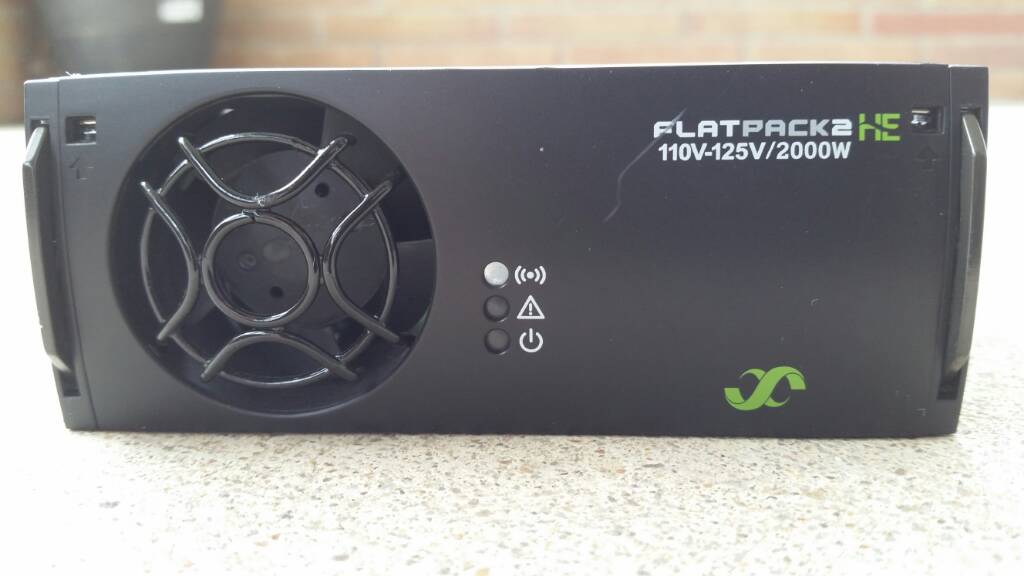
    unsigned char login[8] = {0x15, 0x44, 0x71, 0x02, 0x11, 0x66, 0x00, 0x00};     //HB this is the serial number of the Flatpack + 2 added bytes of 00 each)
    CAN.sendMsgBuf(0x05004804, 1, 8, login);                                       //send message to log in and assign ID=1 (last 04 means ID=1, for ID=2 use 05004808 ) 

//  unsigned char setdefaultvolt[5] = {0x2B, 0x15, 0x00, 0x44, 0x16};               //???? INCORRECT ??? this is the command for setting the default output voltage (Last two bytes, LSB first). 16 80 is the maximum voltage of 57.6 V
    unsigned char setdefaultvolt[5] = {0x29, 0x15, 0x00, 0x9C, 0x13};               // 50.2V
//  CAN.sendMsgBuf(0x05009C02, 1, 5, setdefaultvolt);                               //???? WRONG COMMAND ???? send message to set ouput voltage to all Flatpacks connected to the CAN-bus
    CAN.sendMsgBuf(0x05019C00, 1, 5, setdefaultvolt);                               //send message to set ouput voltage to all Flatpacks connected to the CAN-bus

digitalWrite(23, HIGH); 
}

void loop()                                                                        // main program (LOOP)
{                                                                                  // nothing to do :)
}
 
Hi Camon,

This code should set your flatpack temporarily to 50.2v and 14a. You need to change the serial numbers in two places. Upload to Arduino Leonardo and power the Arduino off/on. Then use the serial monitor to see status

Example
04 1A 00 00 A3 13 F1 00 2C
Temperature = 26
Current = 0.00
OutputVoltage = 50.27
OutputPower = 0.00
InputVoltage = 241


Your flatpack will only have green led n, when this is running.

Code:
#include <mcp_can.h>
#include <mcp_can_dfs.h>
#include <SPI.h>

const int SPI_CS_PIN = 17;
MCP_CAN CAN(SPI_CS_PIN);                                                              // Set CS pin for CANBUS shield
#define INT32U unsigned char
void setup()                                                                          // Initialisation routine
{
    Serial.begin(115200);                                                             // Sets the data rate in bits per second (baud) for serial data transmission to PC.
    delay(1000); 
START_INIT:

    if(CAN_OK == CAN.begin(CAN_125KBPS))                                              // init can bus : baudrate = 125k !!
    {
        Serial.println("CAN BUS Shield init ok!");
    }
    else
    {
        Serial.println("CAN BUS Shield init fail");
        Serial.println("Init CAN BUS Shield again");
        delay(100);
        goto START_INIT;
    }
     unsigned char stmp3[8] = {0x15, 0x44, 0x71, 0x02, 0x11, 0x66, 0x00, 0x00};       // ***** Serial number
       CAN.sendMsgBuf(0x05004804, 1, 8, stmp3);                                       //send message to log in
       delay(10);   
       unsigned char stmp4[8] = {0x14, 0x00, 0x9C, 0x13, 0x9C, 0x13, 0x3E, 0x17};     //this is the command for changing the output voltage 50.2v 14A
       CAN.sendMsgBuf(0x05FF4004, 1, 8, stmp4);                                       //send message to set ouput voltage to all chargers connected to the CAN-bus
      Serial.print("Output Voltage set to : ");
      Serial.println(stmp4[3]*256*0.01+stmp4[2]*0.01);
     
}

void loop()                                                                           // main program (LOOP)
{
    unsigned char len = 0;
    unsigned char buf[8] ;
    if(CAN_MSGAVAIL == CAN.checkReceive())                                            // check if data coming
    {

        CAN.readMsgBuf(&len, buf);                                                    // read data,  len: data length, buf: data buf
          INT32U canId = CAN.getCanId();                                              // read the CAN Id
          Serial.print("0");                                                          // leading zero 
          Serial.print(canId,HEX);                                                    // output CAN Id to serial monitor
          Serial.print("\t");                                                         // send Tab
        for(int i = 0; i<len; i++)                                                    // print the data
        {
            if( buf[i] < 0x10){ Serial.print("0");} Serial.print(buf[i],HEX);         // send a leading zero if only one digit
            Serial.print(" ");                                                        // space to seperate bytes
        }
       Serial.println();
       Serial.print("Temperature = ");
       Serial.println(buf[0]);                                                        //first byte is temperature in celcius
       Serial.print("Current = ");
       Serial.println(buf[2]*256*0.1+buf[1]*0.1);                                     // third (msb) and second byte are current in 0.1A (deciamp) calculated to show directly in Amps
       Serial.print("OutputVoltage = ");
       Serial.println(buf[4]*256*0.01+buf[3]*0.01);                                   // fifth (msb) and fourth byte are voltage in 0.01V (centivolt) calculated to show directly in Volts dc
       Serial.print("OutputPower = ");
       Serial.println((buf[4]*256*0.01+buf[3]*0.01)*(buf[2]*256*0.1+buf[1]*0.1));     // Power is calculated from output voltage and current. Output is in Watts
       Serial.print("InputVoltage = ");          
       Serial.println(buf[5]);                                                        // sixth byte is input voltage in volts ac/dc
//send request for new update

       unsigned char stmp3[8] = {0x15, 0x44, 0x71, 0x02, 0x11, 0x66, 0x00, 0x00};     // *** this is the serial number of the unit
       CAN.sendMsgBuf(0x05004804, 1, 8, stmp3);                                       //send message to request updated figures and keep being 'logged in' or the charger defaults to 53.5 V
       

    }
 

}

/*********************************************************************************************************
  END FILE
*********************************************************************************************************/
 
IMG-20181017-143902.jpg

Hayds13 said:
Hi Camon,

I've edited your code example with commands I used to set to 50.2v. When I try to set my flatpack to 57v in code, it actually goes to over-volt protection shuts down because it goes much higher.

}[/code]

It works¡¡¡¡¡ wow amazing first I programed to 50.2v and works :O before I programed to maximun value 1680 and it works.
Thank you, thank you so much finally I can do a 4kw charger for mi zero DS.
What is the diference between your code and mine?
 
Awesome Camon! Glad to hear you got it working.

Here are the main difference in code:

unsigned char setdefaultvolt[5] = {0x2B, 0x15, 0x00, 0x44, 0x16}; // (Old) setting the default output voltage
unsigned char setdefaultvolt[5] = {0x29, 0x15, 0x00, 0x9C, 0x13}; // (New) 50.2V
CAN.sendMsgBuf(0x05009C02, 1, 5, setdefaultvolt); // (Old) send message to set output voltage to the CAN-bus
CAN.sendMsgBuf(0x05019C00, 1, 5, setdefaultvolt); // (New) send message to set output voltage to the CAN-bus
 
I'm trying to figure out which of the 4 pins on the flatpack S are can L and H. I have flatpack HE working and used this image for pinout, but for flatpack S I can't find a similar image. Closest I could find is this and it looks like Can L and H are suppose to be pins 3 and 4. Just wanted to check if my assumptions are correct.


Edit: Finished soldering it up and yep, my guess was correct. Just need to fit the oled and esp32 inside.
 
I found this floating around and thought someone might want this as some kind of documentation at least.
:arrow:
 
Hi eee291 !

That documentation does not apply to the Flatpack2 HE recitfiers but for the EV chargers.
They can be found here:
https://evolveelectrics.com/collections/chargers

The IP21 look very similar to the Flatpack2HE but they have totally different CAN- protocol.

Best REgards
/Per
 
dakoal said:
jean0 said:
Ian, You're great! The bigger is NCP1015 switcher, the smaller is BC817 transistor.
I replace them, hope it will solve my problem...
Thanks a lot, buddy.

Hi,

I have 4 dead Flatpacks, not opened yet.
jean0, did you ever bring the Flatpack2 back to life with the 2 parts?

Best regards
Bernhard


Hi Bernhard,

Sorry for late answer.
I have 2 dead Flatpacks, I couldn't repair the first one, more parts are damaged, so the device is a big short-circuit.
I bought one more FP, but it is crashed/damaged on its way to me, so its semiconductor parts are good, but the transformers are broken. I'd like to make one FP from the two, but hadn't time to complete yet...

Best Regards,
Je@n
 
Hi,

I've just finished the repair of my one of the 2 FPs.
Now the fan is spinned up, but the red LED is on beside the green and no output voltage.
I can't check the CAN traffic now, but I'm not sure, the CAN connection is necessary for working?
From the manual:
Alarms: Red LED 'on' -> Low mains shutdown, High and low temperature shutdown, Rectifier Failure, Overvoltage
shutdown on output, Fan failure, Low voltage alarm, CAN bus failure

The red LED can be ON for several cases, so I don't know what still the problem...

Best Regards,
Je@n
 
Hi,

I could check just now the CAN traffic of the repaired FP2.
Although the output voltage is only 0.36V, the CAN interface is working.
After I logged in, I get this status: 1E 00 00 F6 FE EC 00 1E
The output voltage word seems to be interesting...
FE F6 is incorrect...

If I try to set any voltage, have no success...
:-(

Je@n
 
Hi jean0,
You're getting 0.36v as the DC output? For a 48v unit you should be getting 53.5v as default when connecting AC (with CAN disconnected). Alternately, the unit could be programmed for another default voltage within 43-5v-57.6v.

Some units don't calibrate well, so if the voltage is programmed to the maximum, it may go into over-voltage protection and get the result you've got(?). You could try re-programming the default voltage to something lower.

Sounds like your flatpack is unhappy. Might be easier to buy another...
Best of luck!
Hayden
 
Hi Hayden,

Unfortunately, every attempt to change the voltage is unsuccesful. :-(
The green and red LED are lit, but interesting, if FP automatically logs out after timeout, the yellow LED also becomes on...
So I don't know if it's software problem or hardware...

Regards,
Je@n
 
pm_dawn said:
I have done a small breakout board for the Flatpack2 and Flatpack2HE
Hi Per.

Have you received your new order yet?

Do they fit in the Flatpack S version too?
 
john61ct said:
pm_dawn said:
I have done a small breakout board for the Flatpack2 and Flatpack2HE
Hi Per.

Have you received your new order yet?

Do they fit in the Flatpack S version too?

Hi !
Yes new boards are in.
50pcs ready for you.

Yes they fit the FP2 S version also.
I programmed a FP2 S unit with the board yesterday.

regards
/Per
 
Remmie,

Any instructions for the Flatpack 2 HE 2000W 110-125Vdc model like on electricmotorcycleforum ?

I tried couple serial number and voltage commands like published here for the 48v models here but i can't get it to change voltage output. I want 116.5Vdc output on one unit of model 125Vdc 2000W HE

eecfbc638ed22cb582cb6230bf95f2c8.jpg


I use the IXXAT USB to CAN compact v1.6 with galvanic isolation.

I just want the correct commands lines that can be sent to permanently change the output voltage.

http://electricmotorcycleforum.com/boards/index.php?topic=7407.30

Thanks alot!!
 
EDIT: Per I don't mean to step on your toes with boards here. As an FYI I ordered a board from Per and it was very good quality and I would recommend them highly. I chose to redesign and tighten up the footprint because the housing pictured below was quite constrained. END EDIT

Would any of you be interested in PCBs for the 1800W Flatpack 2 regular model (not HE)? Not sure if the dimensions are the same but I can post them.

They look like this and can be shipped with or without connectors (for the price of the connectors). AC/CAN Eurostyle headers with a surface mount pad for CAN termination resistor. DC is a 76amp screw terminal by TE Connectivity. I'm ordering our first run and want to gauge interest. Had to reduce the footprint of the board from the guy I originally bought one from (and add connectors).

These boards are spec'd for 240V at full amperage input and output (11A AC in/31A DC Out) This is assuming you're stacking two chargers for a higher DC output.
Screen Shot 2019-04-23 at 2.29.36 AM.png

View attachment 1

Additionally, I may be looking to sell enclosures for the flatpack 2 that hold these boards and have a 20 amp C-19 inlet and molex CAN connection like so:

Screen Shot 2019-04-23 at 2.35.06 AM.jpg

These are still in prototype and will likely have to be green. Let me know if there's any interest! You all have been a great help.
 
yes interested, also for the S

side by side low profile in my case

Able to accommodate the Smartpack where that's desired would be ideal

And always allowing individual per-rectifier AC inputs from separate circuits where limited options are available like campgrounds or friends' houses
 
If you give me dimensions for the smartpack and the S I could probably work something out. The difficulty there will be extra open space around the units. The side by side is definitely doable as are the separate input circuits. The design was originally for two C13 plugs, so 10 amp max per plug and standard equipment for most power supplies and i could swap it back.
 
Back
Top