
Band end away from the display.
You are using an out of date browser. It may not display this or other websites correctly.
You should upgrade or use an alternative browser.
You should upgrade or use an alternative browser.
BBS01B 36V 250W - trying with higher voltage [success]
- Thread starter Wizzeros
- Start date
Thank you fetcher! 
The TVS diode did the trick. It turned out to be a fairly easy fix for the HVC limitation of the BBS02 36v 500w mid-drive system. Anyway, I installed a TVS diode with a 6v breakdown voltage as recommended using a display extension cable.
So I charged my new 36 volt li-ion battery to 49.8v or 4.15v per cell. I hooked the battery to my bike and got 49.5v on my voltmeter. The voltage was 47.3v on the motor side of the TVS diode and 40.6v on the display side. That gave me a 6.7v drop and no Error Code 7. My LVC is 32 volts leaving my battery at a safe discharge voltage of about 38.4v or 3.2v per cell. I have no BMS on my battery pack. The higher voltage is giving me a "peppier" response. I have all 9 PAS settings programmed and I used to do most of my ride on PAS 3. Now PAS 2 with this li-ion battery feels like PAS 3 with my old lifepo4 battery.
So the fix cost about $20. The extension cable cost $10 and the Vishay TVS diode, ICTE5-E3/54, only cost 60 cents but the shipping was $8. I expect to give this setup a good test ride shortly.
RayGo1 said:Thanks for the link.
I ordered several TVS diodes with breakdown voltages of 5v, 6v and 7v to experiment with. Since these are unidirectional diodes, which way should the band on the diode face? Towards or away from the display?
Thanks again for the help. Hope to have results shortly.
Hello RayGo1,
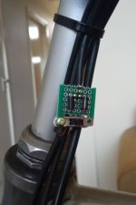
Not sure right now about the polarity, but if you make a mistake it's relatively easy to just rotate the diode. Reversed polarity didn't brake down any diode in my case, but later on I bought bidirectional ones to save some time on assembling. Below I add how it looks in my case. Universal PCB, cheap switch, no heat sink, no enclosure - still works fine.
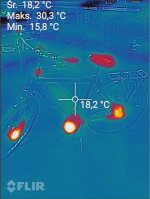
EDIT: I didn't notice your last post. Congratulations! Because I also could not fully discharge my batteries using only one TVS diode, I added another one and a switch, to decide on the voltage drop I want to get. However, I do have a BMS connected to my battery, so it never lets my cells to discharge too much regardless voltage level on the display. I also add thermal camera photo of my bike. TVS diodes (near the steering tube) are getting hotter than the frame, but heat level is less than 30 degrees Celsius in this case. The bike was accelerating and braking only for several minutes before this photo was taken (my friend was testing it for the first time). I don't think it gets much hotter though.
Attachments
Thank you Wizzeros for the info.
I tried to keep it simple. I moved the brown wire and TVS Diode outside the cable to keep it away from the other wires due to possible heat concerns. I then covered the diode with heat shrink wire wrap. I ran this setup for about 15 minutes with no detectable heat problems. I'm guessing the temperature was about the same as yours at about 90 degrees.

I tried to keep it simple. I moved the brown wire and TVS Diode outside the cable to keep it away from the other wires due to possible heat concerns. I then covered the diode with heat shrink wire wrap. I ran this setup for about 15 minutes with no detectable heat problems. I'm guessing the temperature was about the same as yours at about 90 degrees.
RayGo1 said:Thank you Wizzeros for the info.
I tried to keep it simple. I moved the brown wire and TVS Diode outside the cable to keep it away from the other wires due to possible heat concerns. I then covered the diode with heat shrink wire wrap. I ran this setup for about 15 minutes with no detectable heat problems. I'm guessing the temperature was about the same as yours at about 90 degrees.
That looks like a great setup. Those TVS diodes can handle pretty high temps.
In the FLIR pic, the seat looks warmer than the diodes.
RayGo1 said:So I charged my new 36 volt li-ion battery to 49.8v or 4.15v per cell.
Just to correct an error that might be very dangerous if a beginner reads your post:
A 36V battery is a 10S system with 42V fully charged. RayGo1 probably uses a 12S system with a 43.2V battery (50.4V fully charged).
anotherkiwi
100 mW
- Joined
- Nov 3, 2015
- Messages
- 37
I just ordered my diodes to do this mod, my problem is cadence:
- my natural cadence is about 94 RPM so with low RPM motors I get back EMF
- I now ride recumbent and my cadence is vital for comfort and power up to the 25 km/h cut off
- on my upright I had a BBS01 clone (the GSM) and fixed the cadence problem by building a 12S 44v battery which = a 22% increase in motor cadence. I ran that with a standard 36v KT controller and cells charged to 4.15v = 49.8v fully charged, the 50v caps had no problems with that.
Unfortunately that motor broke so I had to buy a BBS01B to replace it and I am stuck with the low cadence problem again. I am going to wire in an on/off switch bypass to the diode so that when I reach LVC I can turn the bypass on hoping that the current will follow the lowest path of resistance...
All instructions above mention a brown wire, with the 500C LCD I have:
1、Red wire : Anode (24v/36v/48V)
2、Blue wire : Power cord to the controller
3、Black wire : GND
4、Green wire : RxD (controller -> display)
5、Yellow wire : TxD (display -> controller)
I am assuming that I need to put the diode on the blue wire?
TIA
anotherkiwi said:All instructions above mention a brown wire, with the 500C LCD I have:
1、Red wire : Anode (24v/36v/48V)
2、Blue wire : Power cord to the controller
3、Black wire : GND
4、Green wire : RxD (controller -> display)
5、Yellow wire : TxD (display -> controller)
I am assuming that I need to put the diode on the blue wire?
TIA
I would try that. There isn't much risk of blowing anything up by trying it. The brown wire on the BBSxx comes straight from the battery and feeds power to the display. If the red wire on the 500C is a skinny wire, then that might be where you want to put the diode.
anotherkiwi
100 mW
- Joined
- Nov 3, 2015
- Messages
- 37
Yeah I was thinking about that after I wrote the above.
If >44.x volts goes through that wire the LCD will assume a 48v battery and show the 07 error message maybe.
If >44.x volts goes through that wire the LCD will assume a 48v battery and show the 07 error message maybe.
anotherkiwi
100 mW
- Joined
- Nov 3, 2015
- Messages
- 37
So I cut open the black shield of the LCD wire and hello! The colourblind Chinese user manual writer has struck again!
I have
Red, so far so good
White
Black, I guess we can trust that to be universal
Green
Brown
The connector shown in the user manual is not a Julet connector but a JST??? flat one.
The good news is that I didn't cut any of the internal wires insulation! Result!
I have
Red, so far so good
White
Black, I guess we can trust that to be universal
Green
Brown
The connector shown in the user manual is not a Julet connector but a JST??? flat one.
The good news is that I didn't cut any of the internal wires insulation! Result!
anotherkiwi
100 mW
- Joined
- Nov 3, 2015
- Messages
- 37
I fully opened in the daylight... 
 (edited image from this post https://electricbike.com/forum/forum/builds/new-builder-questions/77804-wiring-issue-for-a-bafang)
P+ is brown. I will now cut and solder.
EDIT:
And victory!!!! The 500C shows 40.5v and my watt meter shows 46.9v
P+ is brown. I will now cut and solder.
EDIT:
And victory!!!! The 500C shows 40.5v and my watt meter shows 46.9v
So was the brown wire broken inside the harness somewhere?
anotherkiwi
100 mW
- Joined
- Nov 3, 2015
- Messages
- 37
This is the cable coming from the 500C LCD. I just split the sheath near the plug end and spliced in the diode, it is inside a vélomobile so protected from the elements.
Here is the photo and description https://www.velomobilforum.de/forum/index.php?threads/modify-bafang-bbs01b-36v-for-44v.63827/
Today I did my first real road test and it is perfect. We have > 10% gradients all around so being able to spin 90 RPM and help the motor is a big plus. Today I touched and the motor was not even lukewarm - remember it is not in an air flow so no cooling at all. I will mount a fan for when I reprogram the Bafang.
Thank you again so much! This really is a life saver mod for people like me who spin faster than the puny 78 RPM Bafang thinks everyone spins at.
anotherkiwi
100 mW
- Joined
- Nov 3, 2015
- Messages
- 37
A short update:
- the motor is reprogrammed and finally provides some assistance!
- it still runs cool because now that I can spin at 90 RPM I am helping the motor a lot more. I am not sure that it even needs a fan for cooling
- the motor only runs for climbing or very short start up periods, I am driving most of the time above the 25 km/h cutoff speed (EU legal limit)
Similar threads
- Replies
- 48
- Views
- 2,806
- Replies
- 0
- Views
- 123
- Replies
- 4
- Views
- 109