My RC Mid Drive with Single Stage Reduction

I just received a new toy. For testing purposes only.

Turnigy SK8 6374-130Kv


My plan is to NOT use the extra power potential, which might over stress the chain. Rather, I plan to run a 12T sprocket. I'm hoping the motor will produce more Torque at a lower RPM. With the larger sprocket the tension in the chain should be the same. I'm hoping this will run a bit smoother and quieter. We will see if the extra weight is worth it.

935 gm vs 781 gm for the D5035 Orange motor, an increase of 154 gm.

130 Kv vs 125 Kv for the orange motor. I'm not sure if the 130Kv will be accurate, or if the motor will be happy spinning 33% slower than the orange motor. (I may end up wishing for 100Kv)

Rated for 65 Amps vs 45 on the orange motor.

49mohm vs 90mohm on the orange motor. I'm not sure what to make of this...

Overall length increases by 1cm. Stator length increases from 35.6 mm to 45.6mm, a 28% increase. I would expect this to be a good indicator of Torque and Power potential.

I need to change out the connectors and wait for the 12 and 13 tooth sprockets to arrive.
 
I can't wait for your feedback on this motor. I think the 12t sprocket will make the transmission smooth enough. With that low of winding resistance it will suck a lot of current at startup which will probably result in more torque.

I still didn't mount my bt transreceiver to check logging on Vesc. I have a dc clamp meter but everything is enclosed in a box (battery + vesc). On longer rides power drops after a while. I set the temperature cut off start at 60C. I think it's heating to 60c because it's enclosed in a box. I have to think about some form of ventilation.

I did manage to mount that On/Off switch. It has 0.4mOhm resistance which is not that bad.
 
So I was planning to wait for the 12T sprocket before trying out the 6374 motor. Buuut....

I had an 11T sprocket just laying around. So I tried it. :D

The motor bolts right in place of the D5035. It's just a cm longer.

I played with the VESC current limits and settled on 71 Motor, 40 Battery. This gave me watt mater readings of 32.5 Amps and 480 watts at low RPM, and 42.8 Amps and 620 watts at High RPM.

Initial impressions - very preliminary...

The 6347 motor felt a bit stronger and maybe smoother at large throttle than the D5035. It also has a bit of a rising power band. As I pedaled faster, it got stronger. Both of these characteristics may not matter to me in the real world, as I mostly try to stay below about 250 watts. On the other hand, might be fun for a quick thrill now and then... :D We will see.

I would say the 11T sprocket is somewhat smoother than the 9T. The 9T tended to get a bit rough over 280 watts or so. I could feel it in the pedals. The 11T seems to stay smooth to over 380 or so. Overall a smoother setup. I think the 11T is somewhat quieter also.

The VESC did get HOT. Note that I was using much more power than I usually do. Probably for 20-30 seconds at a time. In one case, the VESC was slightly too hot to hold my finger on. I would suggest that anyone who plans to use much more than 300 watts or so for any length of time to be very cautious, and consider the higher power version (VESC 6?).

So which motor do I like better? If they weighed the same, I would vote for the 6374. However, that 154 gm difference may be enough to even things out. At this point, I like them both. I do wish that Turnigy would make a 100Kv version of the 6374...
 
FzBob,

That is all great info, I’m extremely curious how my 6384 will perform in comparison.

As of yesterday all of my components are in and I completed bench testing last night, now I just need to tune the VESC and mount it all up.

As a bonus, I cut two motor mounts mimicking Kepler’s constant contact friction drive from his MTB, I’ll be testing and comparing this to the chain drive.

 
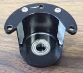
I just received this Sprocket Cover.
View attachment 1


It's made for the Turnigy motors. Provides an additional bearing for support of the outboard end of the shaft. It fits 11 Tooth sprockets for sure. 12T looks like it will work, but be very close, and 13T won't work. I had to drill two new mounting holes and shorten my shaft spacers a bit. I think it gives the conversion a nice finished look. Under $10.

https://hobbyking.com/en_us/motor-mount-cover-with-bearing.html
 
NateTN said:
FzBob,

That is all great info, I’m extremely curious how my 6384 will perform in comparison.

As of yesterday all of my components are in and I completed bench testing last night, now I just need to tune the VESC and mount it all up.

As a bonus, I cut two motor mounts mimicking Kepler’s constant contact friction drive from his MTB, I’ll be testing and comparing this to the chain drive.

A0576A4F-F7EB-44A3-9DB9-6078DD2DCC02.jpeg

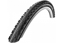
Look forward to seeing the comparison. Plus and minus for both systems that has been previously discussed. Just make sure you use this tire with a mountain bike bike friction drive setup. Yes its a compromise but works well on dry or even damp track and great on the road. Sucks in the mud though.

https://www.chainreactioncycles.com...17l75jTHs29nUyR8vIXOt-lpRsJGuHiBoCNwQQAvD_BwE
 

Attachments

  • download.png
    download.png
    99.7 KB · Views: 4,178
Hey Bob, very impressed with what you've done with drive, so much so I'm going to convert my Yeti SB5.5.

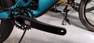
I've just placed the sprocket order with the lovely ladies at Rebelgear. Only change from your design is I'll mount the motor on a plate from the ISCG mount and being running a HXR Easy Shift freewheel crank.

I've got a Flipsky 170kv 6374 motor already so I'll see how that works out.
 
briangv99 said:
Hey Bob, very impressed with what you've done with drive, so much so I'm going to convert my Yeti SB5.5.

I've just placed the sprocket order with the lovely ladies at Rebelgear. Only change from your design is I'll mount the motor on a plate from the ISCG mount and being running a HXR Easy Shift freewheel crank.

I've got a Flipsky 170kv 6374 motor already so I'll see how that works out.
That sounds like it will be a really nice setup! I would love to see pics of the build.

The ISCG mount should be the perfect place to attach a motor mount (for those lucky guys that have one...). Will your motor live in the triangle or under the frame?

I never heard of the HxR crank. Looks like a really clean solution. Sounds like it will be a lot lighter than my SickBikeParts setup (which I shelved due to the weight). Where did you get yours? I didn't see any US dealers.
 
Hi i add my 5 cent to only plus of HXR Easy Shift cranks .

It ez to get no wobbieing chian rings in setup


Only a few grams out . From isis Ti bb isis and thred


I use isis ti manly on my road bike . Ez to find parts .

Kepler may found the best setup. For wight

Big vesc can push alot of motors. No need to care.


Thank you all
 
I've been following this build for some time now and really appreciate all the very good suggestions. A huge thank you to FZBob for all the hard work he already put in. I've bought most of the parts, same orange motor, and will start posting some photos soon. I've asked FZBob some technical questions about the motor and controller, since I don't have any knowledge on the subject. He suggested that I ask the forum. Hopefully there will be some good feedback from people who already tried this.

While researching the VESC controller build by Benjamin, I came across this statement he made.

Change the KV of the motor. Yes, this can be done quite easily without rewinding the motor. Almost all outrunners are connected using a delta-connection. By removing the heatshrink of the motor wires, they can be split up and reconnected in a star-connection. This reduces the KV by a factor of sqrt(3) = 1.73. For this modification, we can use a motor with a KV of 188 * sqrt(3) = 325. There are several hobby motors available close to that KV, so that is no problem. I have tested this modification on several motors and it works really well.

http://vedder.se/2014/10/chosing-the-right-bldc-motor-and-battery-setup-for-an-electric-skateboard/
 
c_saayman said:
I've been following this build for some time now and really appreciate all the very good suggestions. A huge thank you to FZBob for all the hard work he already put in. I've bought most of the parts, same orange motor, and will start posting some photos soon. I've asked FZBob some technical questions about the motor and controller, since I don't have any knowledge on the subject. He suggested that I ask the forum. Hopefully there will be some good feedback from people who already tried this.

While researching the VESC controller build by Benjamin, I came across this statement he made.

Change the KV of the motor. Yes, this can be done quite easily without rewinding the motor. Almost all outrunners are connected using a delta-connection. By removing the heatshrink of the motor wires, they can be split up and reconnected in a star-connection. This reduces the KV by a factor of sqrt(3) = 1.73. For this modification, we can use a motor with a KV of 188 * sqrt(3) = 325. There are several hobby motors available close to that KV, so that is no problem. I have tested this modification on several motors and it works really well.

http://vedder.se/2014/10/chosing-the-right-bldc-motor-and-battery-setup-for-an-electric-skateboard/
Due to the limited drive reduction available to us, about 10:1 at best, and the scarcity of low KV motors, it seems like converting motors from Delta to Wye might be very useful. My (very limited) understanding is that Kv is reduced by a factor of around 0.7, and Torque may increase an equivalent amount (depending on magnetic saturation?).

I would love to hear from motor experts who can clear up my hazy understanding of this conversion.

I would also be very interested in hearing from those who have done this successfully, especially with a VESC controller running FOC sensorless. I tried converting my little Turnigy SK8 5045-150KV motor from Delta to Wye, but I was not successful. I "think" I got it wired correctly, but the VESC barely found parameters. The wattmeter showed a max of 12 Amps and 140 watts, but the motor was very weak (felt like 20-40 watts at most).

Has anyone else tried with negative results?

Depending on what we hear, I might be tempted to try again on my medium size Turnigy SK8 6354-140KV, which could be an interesting motor at 100Kv.
 
Hi Bob,
Couple pics of the bike and HXR
View attachment 1

yeti1.jpg

I got the crankset from Chain reaction cycles online from Ireland. They had them only sale, last I checked they only had one left on stock.

90t sprocket is a few weeks away because I asked for black anodising.

I'll try getting the motor in the triangle area, but would like to keep the motor as close to the crank sprocket to keep it tidy. May need a idler gear for greater chain wrap on the 10t I plan to use.

PS- in the past I've found sdp-si.com to be a great source of#25 sprockets
 
FZBob said:
I just received this Sprocket Cover.
Sprocket Cover a.jpg

Sprocket Cover b.jpg

It's made for the Turnigy motors. Provides an additional bearing for support of the outboard end of the shaft. It fits 11 Tooth sprockets for sure. 12T looks like it will work, but be very close, and 13T won't work. I had to drill two new mounting holes and shorten my shaft spacers a bit. I think it gives the conversion a nice finished look. Under $10.

https://hobbyking.com/en_us/motor-mount-cover-with-bearing.html
I needed to trim the sprocket cover just a bit to clear the chain with the 11T sprocket.

I did find a slight increase in harsh chain noise with the cover in place. I'm not sure if this is due to the cover focusing the sound, or possibly picking up a harmonic vibration/ringing, but in any case, I have removed it for now. At some point it may be worth gluing some foam inside to see if that dampens the extra sound.

Sprocket Cover c.jpg
 
FZBob said:
I needed to trim the sprocket cover just a bit to clear the chain with the 11T sprocket.

I hear that these brushless motor should have the shaft supported externally. This cup is a good idea to prolong the life of the bearings inside.

FZBob said:
I would also be very interested in hearing from those who have done this successfully, especially with a VESC controller running FOC sensorless. I tried converting my little Turnigy SK8 5045-150KV motor from Delta to Wye, but I was not successful. I "think" I got it wired correctly, but the VESC barely found parameters. The wattmeter showed a max of 12 Amps and 140 watts, but the motor was very weak (felt like 20-40 watts at most).

Benjamin says:
having double the RPM and half the torque at a certain power output will cause four times less losses
This means that for a given FET, doubling the current will produce four times the losses
http://vedder.se/2014/10/chosing-the-right-bldc-motor-and-battery-setup-for-an-electric-skateboard/

We are back again to reduction stages .. it seems that higher motor RPM and more reduction is the way to go. More efficient and more power. That small planetary gearbox is really needed (around 3:1) and from 13t sprocket to 78t chainwheel another 6:1. That is 18:1 in total.. and now we are running like half of that.
 
FZBob said:
So I was planning to wait for the 12T sprocket before trying out the 6374 motor. Buuut....

I had an 11T sprocket just laying around. So I tried it. :D

The motor bolts right in place of the D5035. It's just a cm longer.

I played with the VESC current limits and settled on 71 Motor, 40 Battery. This gave me watt mater readings of 32.5 Amps and 480 watts at low RPM, and 42.8 Amps and 620 watts at High RPM.

Initial impressions - very preliminary...

The 6347 motor felt a bit stronger and maybe smoother at large throttle than the D5035. It also has a bit of a rising power band. As I pedaled faster, it got stronger. Both of these characteristics may not matter to me in the real world, as I mostly try to stay below about 250 watts. On the other hand, might be fun for a quick thrill now and then... :D We will see.

I would say the 11T sprocket is somewhat smoother than the 9T. The 9T tended to get a bit rough over 280 watts or so. I could feel it in the pedals. The 11T seems to stay smooth to over 380 or so. Overall a smoother setup. I think the 11T is somewhat quieter also.

The VESC did get HOT. Note that I was using much more power than I usually do. Probably for 20-30 seconds at a time. In one case, the VESC was slightly too hot to hold my finger on. I would suggest that anyone who plans to use much more than 300 watts or so for any length of time to be very cautious, and consider the higher power version (VESC 6?).

So which motor do I like better? If they weighed the same, I would vote for the 6374. However, that 154 gm difference may be enough to even things out. At this point, I like them both. I do wish that Turnigy would make a 100Kv version of the 6374...
At this point, I have four good rides on the big 6374 motor, so I can make a comparison to the D5035 motor. For most of my riding I'm using less than 1/2 power, so I don't notice the power difference. If I really push it, the 6374 has a bit more power. I probably use this for 10 seconds a ride, but it does feel nice. The 11T sprocket is a bit quieter and smoother than the 10T. I need to get around to trying the 12T sprocket.

Do I feel the extra 154 gm? Not at all on the trail. Maybe when loading the bike into my car...

If I were building a lightweight bike, I would still go with the D5035 and 10T sprocket. If I was not not worried about the weight, the 6374 is a bit nicer. Is the difference big? For my use, no. They are much more similar than different, and I really like both of them.
 
fixvid said:
We are back again to reduction stages .. it seems that higher motor RPM and more reduction is the way to go. More efficient and more power. That small planetary gearbox is really needed (around 3:1) and from 13t sprocket to 78t chainwheel another 6:1. That is 18:1 in total.. and now we are running like half of that.
Yup, I hear you :wink: . Every once in a while, I get caught up in the "Gearbox" thought loop. Nice small gearbox, and a small motor spinning fast. That's why I have about a dozen gearbox layouts in Autocad using gears, bearings and shafts from McMaster Carr.

However, then I add up the weight, complexity and cost. Any gearbox system will almost certainly need a freewheel or sprag clutch on the gearbox output, as it will get draggy. If power is increased much at all, (it always happens...) then the #25 chain has to go. Then you can only run about 40T on the chainring, so really about 4:1 max on the final reduction. With 4:1 final, the gearbox will need to handle some torque, so the gears just got bigger. So you can get about 3:1 in a single stage of gearbox before it gets really big. But that only gets 12:1 overall. Buuut... We can use a 2 stage gearbox... (I laid out a few of them) The first stage can be a nice small 3:1, as torque is low. The second stage can be our 3:1, for an overall of 36:1. Yay! Now we can get that 2500 watts! But you better for sure have a freewheel crankset, as this will take your leg off! Now we need 5X the battery, because if we use the power it will eat watt hours like candy. Whoops, our little 5 pound $400 system just turned into 13 lbs and $1000 and a bunch of work if I machine the gearbox myself. :mrgreen: Guys have been doing variations of this on ES for at least a decade. It's just a different animal.

You can "promise not to go over 500 watts", and use the #25 Chain, 10:1 final, 3:1 Gearbox, and a tiny Turnigy SK8 5045-150KV motor. You will still need to source a tiny freewheel on the gearbox output that will mate with a 9 or 10T #25 sprocket (not trivial), or add a freewheel and put the motor drive on the left side of the crank. If you are very careful, machining a plastic gearbox housing and possibly plastic gears (I haven't done the calcs), you end up about where we are now, but with a bunch of extra work, extra cost and extra things to fail.

Then I go and ride my bike... It climbs steep hills at 3-4mph and 100-200 watts, with enough assist to keep me very happy. The motor stays cool, as I rarely need over 200 watts. For my use, the FETs don't seem to get too hot, and I have never tripped a FET overtemp, so I'm not too worried about that particular bit of efficiency. If FET overtemp does become a problem, I will take a look at the larger VESC.

TLDR: Gear reduction is typically not cheap or easy, there's no free lunch!

I hope the above didn't come off too ranty! :D

Note: I have a 22T front chainring, and a 40T rear cog. This is gear reduction which IS cheap and easy! Climbing steep hills with a low power assist requires that you climb slowly, but with reasonable crank RPM. I would recommend at MINIMUM a 34T rear and 22T front or equivalent ratio. Gear the bike down. If you try to climb steep hills at 6mph and 25 crank RPM, both you and the motor (and controller) will be unhappy. (I just realized that I probably didn't stress this enough earlier...)
 
Last year I was interested in converting a motor from Delta to Wye in the hope that it would work better at low RPM with limited gear reduction. I gave it a try with a notable lack of success.

I did some searching and came across this post by liveforphysics which has some really good information on converting motors from Delta to Wye. This is from a thread back in 2011: https://endless-sphere.com/forums/viewtopic.php?t=25136
Torque capability between both Delta and Wye, both the saturation torque, the torque per amount of power going into the hub at the same speed, and continuous torque capability (actually about 2% lower for delta) area all the same for Delta or Wye.

This is because the torque handling of a motor is determined by the copper fill, the winding methods/turns etc can all change the KV which changes the torque per amp the motor produces, but the torque capabilities of the motor remain unchanged unless the amount of copper in the slots changes.

The reason for making a delta-wye switch or series parallel switch is to enable less phase current burden on a controller while operating at low speeds. In other words, it lets you run a weaker controller than would be capable of running reliably with that high of KV wind while at low RPMs, because when you're at low RPMs, you can operate in Wye and place only ~59% of the phase current burden on the fets of the controller for a given amount of torque produced. Note! This has no effect on the battery current per amount of torque produced at a given motor RPM, only on the phase current.

And more in depth info from a PM with liveforphysics

What's a big consideration though between Delta and Wye is that you only get good sinus BEMF for a single option, and when you swap options, the alternative will either get better towards a sinewave (if it was starting from a terribly not-sinus waveform and you got lucky), but most likely it goes from somewhat sinus to a mess. This is pretty hard to predict, but the good news is, it's not so hard to re-terminate the winding ends of a delta into a Wye, and spin the motor up with a drill and watch/capture the BEMF waveform on a scope.

A motor can be well designed (having BEMF that's say >98% of Sinewave) in either Delta or Wye termination style, but impossible to have sinus BEMF in both types. The type that's not Sinus BEMF will be a PITA to maintain torque control, and the BEMF spikey areas will end up making a net reduction in top speed and increase in harmonic losses/heating (small reduction in speed unrelated to the ~1.7x Delta/Wye kV change).

Some RC controllers might be dumb/crude enough to still run similarly poorly between delta or wye for the same motors, but in that case you will want to upgrade to a FOC based system anyways because it will be a huge efficiency and torque control boost.
My takeaway from this is that the benefits are less than I had hoped - It does not increase the torque output of a given motor. There is also a Con that I was not aware of - The BEMF signal may get messy, and sensorless operation may be an issue.

A benefit is the ability to decrease current through the controller. I believe this is similar to switching to a lower Kv motor.
 
Looks relevant - edit - oh it's from 2012. Sorry I'm not awake yet. https://www.electricbike.com/lightest-bike/?fbclid=IwAR2jU-vpqmx2jMkV7h5PDB-8Ql5S6EtYjBSiYkf3LT1jwQbSGQWlLLpduXY
 
falcongsr said:
Looks relevant - edit - oh it's from 2012. Sorry I'm not awake yet. https://www.electricbike.com/lightest-bike/?fbclid=IwAR2jU-vpqmx2jMkV7h5PDB-8Ql5S6EtYjBSiYkf3LT1jwQbSGQWlLLpduXY
Ha! I love it. Under 17 lb for bike AND motor. I think if I sat on it I might break it...
 
FZBob said:
You can "promise not to go over 500 watts", and use the #25 Chain, 10:1 final, 3:1 Gearbox

This sounds good. I would like more reduction for a smoother experience. 10t sprocket is pretty rough and with higher reduction comes higher voltage and less amps which is always welcomed. But it seems that a freewheel is a must.

I might change my mind and try another platform.. My knees are getting worse and I would like assist without pedaling.

The Shimano e8000 is pretty powerful, has reduction embedded in, Sprague clutch and everything, is just missing a throttle.
There are 2 possibilities: fake the torque sensor signal or just use another controller with throttle. I'm thinking of buying a 2nd unit and start tinkering..
 
Here are my notes on Delta vs Wye from my RC Drive page:

Builders of RC Motors Motor drive trains have to pay attention to the wiring. RC motors have 6 power wires coming out of them, one set of wires for each two windings. These need to be arranged one of two ways, "Delta" or "Wye". Generally Wye (also called "star") is more efficient. Wye has 1.73 times less KV than Delta (slower speed per volts), but 1.73 times more torque. In general it's a good idea to stick with Wye configuration for electric bikes as e-bikes need slower motor speed, higher torque, and high efficiency. For Wye configuration, the 3 positive wires are tied together, and the 3 negative wires go to the controller. These 3 negative wires are the phase wires, just like in a hub motor.

http://www.recumbents.com/wisil/e-bent/rc_drive/default.htm

Warren
 
fixvid said:
My knees are getting worse and I would like assist without pedaling.

The Shimano e8000 is pretty powerful, has reduction embedded in, Sprague clutch and everything, is just missing a throttle.
There are 2 possibilities: fake the torque sensor signal or just use another controller with throttle. I'm thinking of buying a 2nd unit and start tinkering..
I hear you on the knees!

If you are looking for assist WITHOUT pedaling, this thread is probably the wrong build. Picking up a commercial E-bike might make a lot of sense. I suspect it would be fairly straightforward to pick off the three phase wires from the motor and connect them to a stand alone controller like a VESC. Emulating the torque sensor with a throttle might be a more elegant solution. I would be a little surprised if a solution is not already available.
 
FZBob, I really like this very simple and clean design. I have been following closely and am thinking about making my own. I also wanted to offer some technical equations for torque and phase amps that could maybe inform some of your motor, current limit, and battery choices.

The key parameters to know for motors are Kv OR Kt and Rm (phase resistance). Kt and Kv are inversely related by the equation below. Units are Nm/A for Kt and rpm/V for Kv.
Kt = 9.55 / Kv

Once you have Kt, you can find the torque output of your motor at a certain phase current. Torque comes from phase current, while power comes from battery current which is what you are reading on your watt meter. We can also try to calculate phase current from battery power and motor rpm or cadence.
Torque in Nm = Kt * Iphase
Power = Torque * w (angular velocity in rad/s, 1 rad/s = 9.55 rpm) so Torque (Nm) = Power (W) / rpm * 9.55

Like liveforphysics said, different winding configurations do not change the output torque capability of a motor, they only change the volts/amps combination that torque is made at. Since you have a fixed phase current and voltage limit from the VESC you are using, you would ideally choose a motor winding that can make the torque and rpm you want within these limits.

For example, you've stated that the orange motor is 125 Kv and 90mohm. If you haven't already, it would be nice if you could verify these numbers yourself since hobbyking isn't always reliable with their specs.
Kt = 9.55 / Kv = 9.55 / 125 = 0.076 Nm / A

You said you settled on 71A motor current limits, so
Torque = 0.076 Nm/A * 71 A = 5.42 Nm

With your 90/11 = 8.2:1 reduction, you are getting 5.42 Nm * 8.2 = 44 Nm at the crank.

You also said 42.8A and 620W at "High RPM". I'm not sure what "High RPM" means, but I'll assume 120rpm for now. Note 620W/42.8A=14.5V which lines up with a 4S lipo battery.
Torque = Power / rpm * 9.55 = 620 / 120 * 9.55 = 49 Nm at the crank which is pretty close to our phase current limit

Note that the fact we are still hitting our phase current limit at "High RPM" makes sense since at 71A, we need to put V = IR = 71A * 0.09ohms = 6.39V into our windings to achieve this phase current. At 120 crank rpm = 982 motor rpm, our bemf is 982 / (125 rpm/volt * 15V) * 15V = 7.9V. This means we need to put 6.39V + 7.9V = 14.2V into our motor which is still under our battery voltage.

Perhaps you can use some of the above math to help explain why different motors feel different from each other. I would be interested in what you are trying to optimize when you play with VESC current limits as well as what low and high rpm mean when you are reading your watt meter.

Since you have plenty of voltage headroom on your VESC but are butting up against the current limits, lowering Kv will help to move the volts/amps combination away from the current limit.
 
It seems that wiring the motor to a star connection should eat less current at an increased voltage. Which results in less electrical losses and an increased efficiency. The FETs on the VESC will be more happier too.

I was playing around with the bike on a stand and checking the current consumption by pulling the brake. Max current taken from battery is in the range of 24-27A measured with a clamp meter. Battery voltage was around 16v, but under load it drops to under 15v. Let's say max power achieved was ~350W. Then i hooked up the pc to VESC and turned on the realtime monitor. At maximum load the motor sometimes stutters. I don't understand the exact cause. Current limit set too high but not enough voltage maybe ?

2zrg5te.png
 
fixvid said:
It seems that wiring the motor to a star connection should eat less current at an increased voltage. Which results in less electrical losses and an increased efficiency. The FETs on the VESC will be more happier too.

Read around. Changing Kv by winding or star/delta changes does not change torque capacity. Eating less current at an increased voltage does not result in less electrical losses in the motor since in order to decrease Kv/increase Kt/reduce amp draw, you increased Rm by the exact amount that results in the same I^2R losses for a given torque output.

The only way to make more torque from your motor is by using stronger magnets, improving stator iron shape, improving copper fill in the windings, or improving cooling abilities.

It is true that the fets on the VESC will be happier which is why I said to match the motor winding to the controller.
 
Back
Top