Ampera/Volt inverter with Lebowski brain

Lebowski said:
Dont thjnk parallelling two output stages is a problem, but I would definitely use all 6 current sensors then ! You can add the current sensor outputs using resistors.

Hm... so i could just connect sensors in the same order they are connected to outputs. I.e. sensor A1 of one IPM would be parallel with sensor A2 on the other IPM and same for sensors on phases B and C. Where do the resistors come in?

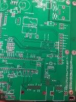
See here i already use Volt connector J1 so sensors could be directly paralleled. Do you think i would have to add anything?
 

Attachments

  • IMG_20190719_224322.jpg
    IMG_20190719_224322.jpg
    221.4 KB · Views: 3,801
I think i used 1 kOhm and 10 nF in the (single) current sensor lines... for two sensors each sensor would need its own 2.2kOhm resistor in series with its output and then connect to the 10 nF. The resistor is a bit higher because two 2.2kOhm's in parallel is roughly 1 kOhm.
This way by using equal resistors the current sensor output voltage averages out... effectively in the controller IC you can then enter half the V per Amp of a single sensor.
 
Lebowski said:
You dont, just have to match wiring length and trust inductance and ptc to equalize the currents...

What if they don't share current properly?
 
It has been done by some guys in the Ukraine I think. A video on YT showing an Ampera/Volt inverter running a Nissan Leaf motor in a Peugeot van. There are a couple of videos showing the inverter, it is hard to be certain but it looks like they are driving the 6 half bridges in closest pairs ie 1 and 2, 3 and 4, 5 and 6. It makes sense even if it does mean you have to rewire the the bridge outputs, in any case that is how I plan on doing it.

[youtube]_nF5oRZclFE[/youtube]
 
Hah, great minds truly think alike.
I see he used some lenght of cable before he attached in paralel. I wonder if this is what Paul was describing when he told about his AC controller being used as DC motor controller. He paraleled uppe and lower IGBTs to get like 1000A push pull unit. He told he had to use some length of cable because of some IGBT vibration/pulsing damping? I didnt quite follow, but now it seems i see another iteration of this.
Bas, you have any comment on what to use? Either very short clamps to paralel IPMs or some 400mm cable lenght before paralel connection, similar to what they use.
 
Lebowski said:
I think i used 1 kOhm and 10 nF in the (single) current sensor lines... for two sensors each sensor would need its own 2.2kOhm resistor in series with its output and then connect to the 10 nF. The resistor is a bit higher because two 2.2kOhm's in parallel is roughly 1 kOhm.
This way by using equal resistors the current sensor output voltage averages out... effectively in the controller IC you can then enter half the V per Amp of a single sensor.

Nice one!
I can lead additional wire from lower connector and i can solder 2K2 inline. I have split sensor lines with holes just for that :).
I will have to split driver connector leads to command both IPM. I think i will just design a new board and put everything what i learned on it.
What about 4K7 GND drain caps? Those i should use for each sensor line yes?

A
 
Lebowski said:
Maybe show a quick schematic of your intentions wrt the current sensors and the 2k2 resistors ? And I dont understand the bit about the 4k7 capacitors ?

Sorry not caps, but resistors. 4K7 per channel is what Volt main board has installed just after the connector. So i replicated it and it does seem to drain most of the hash away.

Well schematic is mainly yours with a separate branch from the 10nF cap. Also i will have to branch driver signals into each IPM connector.
 
I am on to tuning out the rumble and shaking in the Leaf motor.
I am using Chevy Volt inverter with 600A 600V IGBTs

Leaf motor should pull out with power, but it doesnt happen. We keep getting the shaking and surge just before driveoff into a steep hill. Are that position sensors or bad settings?
Motor does drive off with gentle throttle, but with rougher handling it conks out.

I tried changing lots of parameters. Mostly i got a good behaviour with motor parameters 178uH and resistance between 42mR to 76mR. Outside that parameters motor does not behave good.
I attach parameters for our fallback settings that work.

When i started to try other parameters i watched Arlos videos. He says i would have to cycle through parameters to update them. Can you explain that to me? How to update parameters after i change some current or motor settings? What parameters are to be updated at that time and how?

tnx
 

Attachments

  • Lebowski Leaf settings stane.docx
    18 KB · Views: 83
Current sensor offsets are some -/+13pt
Hall sensors are at value 6 in general. I cant get them to be 7. And RLS sensor was set to 0 position using current through 2 adjacent phases as per RLS procedure. Do you think 6 is not confident enough?
 
Confidence at 6 shows there is a lot of noise on the hall signals, if you scope them theyll probably look messy..

Calibrating the sensor to 0 is not necessary, as the controller IC can deal with offset. The number of pole pairs in the RLS and motor should match though.
 
Certainly, Leaf motor is 8 pole design. I purchased 8 pole encoder simulation, so the signal is correct.
I can scope signals but only on the inverter side. They are connected inside motor. Cable shield is connected to car GND on the inverter side. Do you think the problem is the sensor? Would different decoupling caps on sensor lines help anyhow? I use 10nF caps now.
RLS encoder has its own output drive. Each output can drive 24mA. Would that interfere with the system as a whole? I could add additional pullups on the controler end if you think that would be good.
 
Lebowski a question if you please.

What would functionally happen inside controler if i pressed reset button while motor would turn at 8000RPM?
I consider this rather high hazard because i would have a battery of 380Vdc nominal and motor backEMF voltage will be higher at that RPM.
To protect against inadvertent power section failure I decoupled DC contactor from controler brain, it is enabled by another uC when votlage goes past some value
Is there something more to be done?

tnx
 
When reset is pressed it will shut down the output stage, turning off all FETs/IGBTs .

If you are using field weakening and motor speed is higher than the battery would normally allow, roughly the at that moment used field weakening current will be delivered by the motor to the battery (via the FETs freewheel diodes). This will amount to braking the motor as if you are running regen.

I would say normally nothing needs to be done...

The danger is when the motor voltage (due to high speed) is much higher than the FETs of the controller can take, AND the main battery fuse blows. Normally with field weakening the FETs do not see the high motor voltage, only the limited battery voltage. But the main fuse blowing would show the high motor voltage to the FETs, probably blowing all of them in an instant. If they all short out your motor at high speed would be completely shorted out... to protect against this you can put a high amp fuse in each of the motor wires coming out of the controller.
 
Guys be careful with this.

I read the last 2 posts and have a couple comments.

1 Most EV fuses are slow blow so take that into consideration
2 You should use a smart fuse (Tesla Pyro fuse)
3 The instant regen if you fault the controller is brief and you will be surprised how its a non issue.

You can do a couple other things 1 keep the RPM limits low so you don't use a lot of Field Weakening also if it looses sync and you are driving the car at the time hit the breaks hard and get it out of that zone where Motor voltage is higher then battery voltage.

When we were shooting the discovery channel episode. I was going about 200km/h and Max speed with no field weakening was 130km/h so it was a LOT of FW. Needless to say it konked out and lost sync. It almost slammed my head into the steering wheel I knew what was going on and it lost sync so I slammed the breaks and thought I was going to be running from a car on fire. But once it slowed down to ~ 130 it recaptured the motor and was back running again and everything was fine. I was lucky. But its suprising how many times I lost sync above 130km/h

This testing stuff is why I build a new dyno!
 
Tnx Arlo i really need to hear this from someone with experience with PMSM. I only done this with ACIM and however you rev that motor is a piece of iron if you turn off excitation.
The way you are saying it i identified couple of hazards.
1. DC contactor dropout when in FW region. This would blow my PS for sure
2. Conking out at high speed with massive regen. All power goes straight to the battery.
3. un/intentional controller reset by EMGCY button. What exactly would happen here? Would it regen through IGBT reverse diodes? How much?
4. Main pack fuse is not so much of a consideration since i will use oversized fuses anyway. Fuses are there to protect car against battery short circuit fire not to protect equipment on DC link against overload.

1. I can fight that with 3rd IC keeping the DC link alive above some preset voltage (usually precharge threshold)
2. I can try to fight that by trying to decouple and tune out sensors. Or in case of instance to apply the brakes.
3. Would it change that story to freewheel the core? I mean what if we would setup controler so watchdog would not drop it out but would rather freewheel it at last valid speed which would slowly taper out? Like having a small amount of reverse slip. Could that be done in current setup? I belive this would drastically lower the energy at such event.
4. I would fight that by preparation and not going there at all.

For now i would like to make a daily driver with speeds up to 160km/h and stock battery voltage. This will be for learning. Later i would try and double the power stage with both sides of Volt inverter. Then i will consider point 4 further.
 
Came across this thread and just wanted to say: great work so far. :thumb:
I will follow this thread. Good luck with the build.
 
Well i have made it.

While i was trying to decypher Leaf AC compressor serial bus or whatever it uses i was getting nowhere. So i decided to just build me a compressor drive.
I will use Volt inverter, so inside is one Aux controler with enough power to drive compressor. It was originaly intended to run Aux hydraulic pump to keep transmission under pressure when car is stationary. When Tom and I inspected this drive we figured it has 50A sensors and while i was putting 10A load onto it it didnt get too warm. https://www.diyelectriccar.com/forums/showpost.php?p=1017183&postcount=84

Now i have one Lebowski board inside connected to drive connector and Leaf compressor on the other side. I must say cables on that compressor are tiny. Just two strands of 0.20mm2 wire. I think max power on compressor is actually 10A.
Look at it running. Noisy boy! https://www.youtube.com/watch?v=RM0WT1HOQl0

Also Lebowski measured motor parameters... 5100uH and 600mOhm per phase.
Soon i will get Prius compressor and will also try to run it.

Now what i need to develop is a CAN AC controller with some temp sensors and slow RPM ramp logic to simulate throttle ramp up. Also i will only use reset pin only to switch the drive ON. Rest I/Os are not needed it seems.
 
Well i have here Prius gen2 AC compressor. I love it. It is a simple motor on scroll compressor. It has exterior 3phase cables that one can connect to any inverter. I spent like 5 minutes on Lebowski inverter calibrating motor resistance and inductance. And it ran!

While i think other compressors are more powerfull, this one lends itself better to DIY use.

Prius AC compressor Lebowski parameters:
Motor Inductance: 2550uH
Motor phase resistance: 500mOhm

Voltage used 360Vdc
Current set at 20Arms and max battery current 10A.
EDIT: https://www.youtube.com/watch?v=xo-NJ9fLtgk
 
Did you have any problems with the main motor being sensitive to the R and L values ? Do you have a pickit ? We can try to remove this sensitivity with a small code change. It'll be a bit experimental though as i have no more test setup here at home... now with the virus i repurposed my workbench for home office/remote work. So i cannot test-run any code updates... but its a relatively small change.
 
Lebowski said:
Did you have any problems with the main motor being sensitive to the R and L values ? Do you have a pickit ? We can try to remove this sensitivity with a small code change. It'll be a bit experimental though as i have no more test setup here at home... now with the virus i repurposed my workbench for home office/remote work. So i cannot test-run any code updates... but its a relatively small change.

Yes i have PICKIT3 here. But i must warn you, i know a bit about C+ programming and absolutely nothing about assembly language :cry:

That said there is a lot of difference in values you get from FOC testing. For example i use 2550uH for inductance and the value moves from 2300 to 2700uH. While i measure phase resistance i get 1200mOhm so then i split it for 600mOhm per phase. System measures only 60mOhm! This is about 10x the difference. But my hand set value works very good. If i reduce L by more than -200uH than motor tries to jump more. If in turn i increase it by +200uH i get sluggish response.
While if i move from the 600mOhm value for more than +/-100mOhm motor just stalls after some revolutions.

Well as you see from the video the motor is trying to take off under some load and conks out the first time. Then i quickly pushed reset and it take off good. What would your correction do? Teach me master 8) .
 
I can make a code change and send you a hex to try... what it will do is explained in the thread where the code is explained, this is one of the improvement suggestions in that thread...
 
Lebowski said:
I can make a code change and send you a hex to try... what it will do is explained in the thread where the code is explained, this is one of the improvement suggestions in that thread...

Please send me a copy of the modified code. With the Nissan Leaf motor I found leaving the inductance alone and just increasing the phase resistance until the instability disappeared worked well. With the much smaller Hyundai HSG IPM motor I hardly had to change the phase resistance at all to get the motor running beautifully.
 
Lebowski said:
I can make a code change and send you a hex to try... what it will do is explained in the thread where the code is explained, this is one of the improvement suggestions in that thread...

Yes please send me the hex file. I am sorry i didnt want to whine about assembly. I want to learn.

tnx
 
Back
Top