You are using an out of date browser. It may not display this or other websites correctly.
You should upgrade or use an alternative browser.
You should upgrade or use an alternative browser.
Serious FOCer (84V VESC 6 based controller)
- Thread starter shaman
- Start date
wil
10 W
Hey top to bottom phase FETs again!
I thought you went against that in the cheap FOCer because of induction concerns?
Also is that a "4 layer" PCB made of two sandwiched PCBs I spy, or just a rendering thing?
I thought you went against that in the cheap FOCer because of induction concerns?
Also is that a "4 layer" PCB made of two sandwiched PCBs I spy, or just a rendering thing?
shaman
1 kW
You spy almost correctly. It's two 4-layer PCBs sandwiched together.
So being honest here, I've been basing FET layout on typical ebike controllers without having any real knowledge of proper low inductance, low noise, and symmetrical layout of the power stage. I've done some homework and I have been getting schooled by the likes of @marcos, @zombiess, and @HighHopes. I feel I've come a long way. I also feel like I have a long way to go before I can play with the big boys. Either way, I think can safely play in the <10kW range for now.
So being honest here, I've been basing FET layout on typical ebike controllers without having any real knowledge of proper low inductance, low noise, and symmetrical layout of the power stage. I've done some homework and I have been getting schooled by the likes of @marcos, @zombiess, and @HighHopes. I feel I've come a long way. I also feel like I have a long way to go before I can play with the big boys. Either way, I think can safely play in the <10kW range for now.
shaman
1 kW
The bottom one is purely dedicated to DC link and motor phase connection. The other is dedicated for control and gate driving while also assisting slightly in beefing up the motor phase connection.
Looks a lot more "vesc-like" now, I guess for the right reasons. Though this new design seems more complicated to build (2 pcbs!) and I'm not sure side cable exits are interesting for regular bike use: most controllers would sit in the triangle, and hence be as narrow as possible. Hence the usual design with cable exits at the top or bottom of the controller. I think the 70mm width could fit, since it's only 5mm wider than a 18650 cell, or exactly the width of newer 21700 cells, even though 65mm width would be better for the matter. Where I'm more worried is finding an proper case for the beast. Should be something like 25-30mm x 130mm outside, with one finned beefy plate over the FETs and the rest 1.5mm walls, ofc waterproof.
shaman
1 kW
qwerkus said:Looks a lot more "vesc-like" now, I guess for the right reasons
It's flatter...but that's about it. Still using TO-247s. Still using film caps.
qwerkus said:I'm not sure side cable exits are interesting for regular bike use
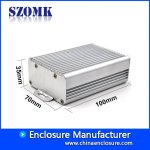
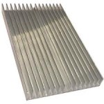
There would be plenty of room in an off the shelf extruded aluminum enclosure (similar to the one above) to have the power/motor cables come out wherever. This controller only sits 14mm tall so there would enough space on the Z axis to fit cables going any direction. Slap cable glands or grommets on the ends and run the cables though them. Yes also an approach could be just a beefy heatsink plate (see below) that you then put a 3-sided enclosure over. The DIY kits I intend to sell will allow you to come up with whatever enclosure scheme you want.
If you're worried about dimensions, then the Little FOCer will be less wide and long. Conservative power limits might be 2.5kW continuous and 5kW bursts at 75V. If that's enough for you, then it will be easier to fit wherever you need it. Don't forget dual motor operation is easy. Stacking Little FOCers in an over/under configuration for dual motor control would still be small solution.
The esk8 market is much harder to please when it comes to enclosure dimensions. They don't want anything above 18mm tall and they stash the controllers in a plastic box along with the batteries underneath the board with no airflow. This is a challenge for me since there's no off the shelf solution for this that I can find. For this specific application, I will be investigating a custom sheet metal enclosure design and thermal potting...
Andrewol said:do you know estimated boom costs to build Serious FOCer and little brother? Perhaps group buy would be preferable.
BOM costs will be between $30 and $40 in quantity. This number also depends on which FETs I end up using. I'm investigating a certain manufacturer at the moment. I've requested samples and will be verifying the FETs in the lab potentially with a curve tracer. I will be putting these through a vetting process.
Because of my business aspirations, it may be less of a group buy thing and more of a pre-order or waiting list thing. Stay tuned as these details form over the next couple of months.
shaman
1 kW
That BOM is only considering electrical components and PCBs. It's also a very rough estimate. I need more time to finalize the design before trying to come up with a more accurate BOM
shaman
1 kW
Something like that. I'm working to keep costs as low as possible. This means keeping things easy to assemble. I may be turning my garage into an assembly house for initial stocking and packaging. I need to have high quantities made before I can justify outsourcing the assembly. That all depends on initial success.
I need a quick clarification: when you're talking about "little focer", its this one you mean ? Or a smaller version of the serious focer ?
Love the dual motor option; stacking thin controller over each other would be quite an improvement indeed.
For the rest: I admire the effort to try an please two communities. Looking at the original VESC, I was under the impression that bikes and skates are just two different worlds; but I you can offer a viable bridge: by all means!
shaman
1 kW
qwerkus said:Or a smaller version of the serious focer ?
This. Just imagine the Serious FOCer but but with 6 TO-220 FETs and closer to 50mm x 100mm x 18mm. The Little FOCer is the one I'm really pitching to the esk8 crowd. Dual 2.5kW/5kW controllers should be enough power to make their death planks go fast.
The Serious FOCer is more for the ebike crowd with the more powerful single and possibly dual motor configuration. Ebikes have more room to spare and easier to shop for when it comes to enclosures.
qwerkus said:Love the dual motor option; stacking thin controller over each other would be quite an improvement indeed.
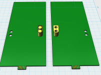
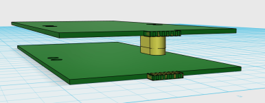
Disclaimer: Extremely crude model.
Glad you like that. Strategically placed XT60 connectors directly soldered to the boards should enable this. Female on one and male on the other. Then make controller sandwich. Connect ribbon cable or something for the comms. Headers can be added throughout the board layout for increased mechanical hold. The DIY kit would be perfect for allowing the customer to implement this.
qwerkus said:I admire the effort to try an please two communities. Looking at the original VESC, I was under the impression that bikes and skates are just two different worlds; but I you can offer a viable bridge: by all means!
Thanks! Yeah I'm trying my best to achieve this with minimal changes to the design.
shaman
1 kW
The render I posted was for the Serious FOCer. The Little FOCer is just a version of the same thing but with TO-220 FETs. The TO-220s are smaller and allow for me to shrink the board down a little. Yes the Little FOCer might have the XT60 connector for the over/under configuration. Yes I can lay down the film caps if it helps but I still have the connector board taking up some height no matter what. Power is conservatively estimated to be 5kW continuous and 10kW peak for the Serious FOCer. 2kW/5kW respectively for the Little FOCer. These numbers are at a 75V volt supply. Hopefully ERPM is as high as the original VESC 6 which has a limit of 150000 ERPM
Can the power little one be increased to 3kW\6kW respectively? 75V will be nominal or maximum?shaman said:2kW/5kW respectively for the Little FOCer. These numbers are at a 75V volt supply.
shaman
1 kW
Andrewol said:75V will be nominal or maximum?
Serious FOCer (84V VESC 6 based controller)
Features:
15V to 84V operation
Max is 84V(20s). That will be verified in testing. I'm assuming batteries will sag down a bit during high current loads. Calculating power at 75V loosely accounts for this.
I can't just arbitrarily increase advertised power. Everything I've stated so far is untested. Real limits will reveal them self in the lab. I'm just assuming current limits that are related to the TO-220 and TO-247 package and leg current limits.
marcos
1 kW
- Joined
- Nov 19, 2016
- Messages
- 348
You want to know exactly which enclosure you are going to use, with exact dimensions, 3D model, availability, and cost, and make sure you include the post-processing it needs for connector cutouts.
This process can unveil some challenges I see like how to expose the JST connectors, or how to screw the mosfets into the heatsinking surface.
Is the enclosure fully metal? That might prevent you from embedding a nrf BLE radio that your customers may want.
This process can unveil some challenges I see like how to expose the JST connectors, or how to screw the mosfets into the heatsinking surface.
Is the enclosure fully metal? That might prevent you from embedding a nrf BLE radio that your customers may want.
shaman
1 kW
marcos said:You want to know exactly which enclosure you are going to use
Working on it and I'm narrowing it down. Im pretty sure I can make the board mounting scheme not depend on utilizing the slide rails of these extruded enclosures. This allows a bit of flexibility. I've been shopping pretty hard for companies that offer off the shelf extrusions for enclosures. The ones I'm interesting in cover the cost, availability, and post processing aspects pretty well.
marcos said:challenges I see like how to expose the JST connectors, or how to screw the mosfets into the heatsinking surface.
JST connectors are being moved to the front so they can be accessed from the end plate. The plate can have CNCed slots for the connectors.
The MOSFET thing is a challenge. Screws will have to come from the outside in. Things like rivet nuts pushed into the PCB might help.
Yes the enclosure is metal. Typically the esk8 crowd connects their modules externally but I do prefer internal placement for other applications. I may have to find by experiment as to whether or not the BLE signal can make it through well enough to travel a few feet.
shaman
1 kW
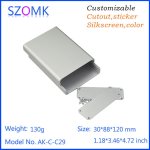
One thing that may help with the MOSFET mounting issue is using these split style extruded enclosures. It would allow better access for assembling the unit. They only thing is that these typically don't have a lot of fins or seem to display good heat sinking features. Not sure if thats a valid concern or not. Maybe potting the controller with thermally conductive compound may help compensate. Probably expensive though.
shaman
1 kW
Andrewol said:or integrate a heatsink in controller's housing.
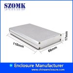
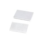
pictures are for reference and not representative of what may actually be used.
Ok. So maybe beef up the split style enclosures with an external heatsink plate coupled to the bottom. It can be mounted with the same screws used to mount the FETs and PCB. Thermal paste could be used in between.
This concept can possibly apply to both FOCer models with the Serious FOCer having a larger enclosure and beefier heat sink plate.
If heatsink will be coupled to the bottom plate the last may flex from screws torque as it's thin and won't provide good contact area. Also there will be too much of thermal resistance between mosfet's die and external heatsink. Use the heatsink as a bottom instead. The best way would be to calculate power dissipation of the mosfets and choose appropriate size heatsink.
shaman said:rBVaGFZ4vnyAC5PNAAJ5ck6f2X8987.jpg
One thing that may help with the MOSFET mounting issue is using these split style extruded enclosures. It would allow better access for assembling the unit. They only thing is that these typically don't have a lot of fins or seem to display good heat sinking features. Not sure if thats a valid concern or not. Maybe potting the controller with thermally conductive compound may help compensate. Probably expensive though.
Yeah; szomk (how to do pronounce the name?!?) is rather expensive. Also, this split type is tricky to seal.
Similar threads
- Replies
- 11
- Views
- 1,823
- Replies
- 55
- Views
- 14,110
- Replies
- 182
- Views
- 18,780
- Replies
- 66
- Views
- 12,639

