APL's DIY axial-flux motor

APL said:
I have been thinking about it though. (end windings) This is one half baked idea I've been trying to work out,..sort of
a radiator style core. End turns get reduced, and radial turns are doubled. I'm not sure how the magnetics would wind up
being yet, and I'm probably missing something major, but I'm trying.

Radiator Core 1.jpg

Sorry if I'm saying something stupid since I'm quite a noob in magnetics, but by doing it this way won't you end up having 3 electromagnets, two being north and one being south oriented (or vice versa)?

2.png
 
APL said:
Another idea I had for the rotor was to use a one piece tapered shape for minimum weight, and a more organic look.
Still need to know how thick though, and it would be more machining, so maybe not on this motor,.. but we'll see.
Taper matches the trapezoid taper.
Looks good :thumb:
Just to clarify if we talk about the same as you metioned that "it matches the trapezoidal taper":
if your magnets are 20mm on bottom and 30mm on top, you would have to make it 20/3 = 6,66mm on the inner diameter and 30/3 = 10mm on the outside.
End turns away from steel don't contribute, but end turns next to steel should contribute to the power of the overall core
flux, I would think.
For PM motors i believe that it doesn't matter if there is steel next to the endturns since the Lorentz force is 90°to the direction it spins and so it doesn't add to torque. Thats my opinion but i might be wrong.
Have you asked miles from here if he could help? Some years ago he has been quite active in motor topics with FEM simulations and EMETOR program.
Having someone with the knowledge of how to use this software would bring light to the day.
 
APL said:
I have been thinking about it though. (end windings) This is one half baked idea I've been trying to work out,..sort of
a radiator style core. End turns get reduced, and radial turns are doubled. I'm not sure how the magnetics would wind up
being yet, and I'm probably missing something major, but I'm trying.

The configuration in the drawing will have 3 poles, N,S,N like that. If the magnets match spacing it will work. This would be a type of concentrated winding. A single turn might be hard to work with though. Adding more turns would be hard without creating more end turns. My old BMC motor had a similar winding pattern (I don't know the technical term for it). 3 poles were wound with a single piece of wire so they all energized at the same time. The rotor would line up with the middle pole if you just apply DC to the wind. This was a way to minimize the copper length going from one pole to the next.

The part about end turns not contributing to torque has always been debated but a good simulation should tell the story. I recall there was a paper somewhere earlier in this topic that described if the brim of the tooth covers the winding, then it will contribute. They were saying the core losses in the powdered iron material were greater than silicon steel laminations but it was more than compensated for by lower copper losses by having shorter wire length around the core. Clearly any copper that is outside the core will not contribute, so that should be minimized.
 
I think your right Dui, ni shuo de dui, I haven't really got very far with it yet,.. still in the thought stage. The Drawing
helps to visualize. Clearly, something else needs to happen here, and I need to pay attention to Lorentz directions,
It's what happens on the face of the core thats hard to imagine for me.

Fechter, I show one winding, but it's still in progress, and the wire should cross over to the other side, on the bottom,
and wrap around again for several windings.
This drawing is also an exercise to try and figure out how to draw wire coils,.. I'm not doing to good at the moment,
but I just learned something yesterday that might be a game changer.

The brim of the core is still a mystery to me as well, what is it really there for,.. how much, how thick, what shape?
Theres a lot to know about it yet. I've always thought that the windings 'all' contribute to the core face,.. either N or S,
as a monopole, and that the most concentrated flux was in the center of the face.
Lower copper losses, due to a smaller core, makes sense, and gives more reason for the brim.

Madin88, the 6/10mm thickness of the iron would be to avoid saturation at full current, I would assume. But what about
at less current,.. say half as much, would it follow that it could be reduced to half the thickness?
Or maybe I'm missing it all together, and it has more to do with PM thickness, spacing, and T's.

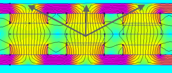
I was also wondering if some of the material between the PM's could be reduced or cut away slightly, as I see an area on
Thecoco's FEMM drawing that shows low flux on the back side of the back iron, in between the PM's.

femm.png
 
APL said:
I was also wondering if some of the material between the PM's could be reduced or cut away slightly, as I see an area on
Thecoco's FEMM drawing that shows low flux on the back side of the back iron, in between the PM's.
Yes, as long as you have enough mechanical strength in the back iron, you could do a V-groove or something in the middle of the magnet where the flux is much lower.
 
That's good news! It would have to follow FEMM, but it's good to know that some extra steel can be trashed. :thumb:
Maybe even be turned into a cooling feature somehow.
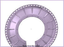
Heres a quick modification on the last drawing that shows what it might look like, sort of,.. I had a hard time
figuring out how to show it.

Back Iron fine tuning relief.png

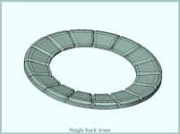
The next drawing takes it even farther, and uses single pieces, for the minimum approach. But they would all need to
be connected to a disc somehow,.. so probably not to much to gain in the end.
Just a thought.

Seperate back irons..png
 
It's extremely rare to see back iron that is optimized. Most designs just go for overkill (or not) thickness and the simplest to make.

Now we need a 3D printer that can do silicon steel parts. They actually have them but a bit out of our price range.
 
This is a little OT, (couldn't help myself) but are you sure you're just building a motor? Looks like it might be a little more advanced.... ;)


file.php

stargate_sgc_unending.jpg


that said, i'm enjoying watching the evolution of these motors. :)
 
APL said:
Heres a quick modification on the last drawing that shows what it might look like, sort of,.. I had a hard time
figuring out how to show it.

The most optimized design would be a V-groove that starts with 0mm in the middle of the magnet and up to 1/3 where it ends, but that would be a lot of effort for reducing weight.

How many watts this motor shall be able to deliver? didn't you say that 500W would be enough :lol:
 
It is looking a little spacey! :lol:

Well, take a page from auto industry design, (so I've heard), is to take a concept to the farthest conceivable point,
and then back it off about 1/3, for a reasonable futuristic design.

It's probably the 'gram hugger' stage in the early biking days,.. spending untold hours of thought on how to loose more
weight on my bike. :oops: (we've all been there) I have an aversion to steel.

One thing about segmented back iron though, is it can be made out of SMC material, making the whole motor SMC,..
cores, magnets, and back iron.

Something to keep thinking about anyway,..won't happen on this motor, but could show up on V3. Maybe by that time
I'll have some skill's with a FEMM program, and can get a better idea of what exactly to do.
I'm working on a new drawing showing how it might be made,.. I like the idea, but it it needs lots of help.
 
The cores for this motor are designed, but the problem I'm having right now is that this DSM program I'm using only
exports in STL, which is a 3D printer format.

CNC machines use 'solid' format's like STEP, and IGES. So either I need to convert STL to STEP, (which can be done, but
not easily), or, download another 3D program like OnShape, learn to use it, and redraw the core in that... which will export
in STEP. That's probably going to take me a while.

So, I'm dead in the water at the moment,.. I have some friends that can probably help, and I need to pursue that,..but
maybe one of you have some knowledge in this area, and can shed some light on how to proceed?
 
Your program really only exports STL? That's very unusual.

APL said:
either I need to convert STL to STEP
Forget it. Even if you find something that does this for you, the results will be awkward. Exporting to STL means a loss of information. STP/IGES contain mathematical information, such as circles being defined as circles. STL on the other hand are made of thousands of triangles, so circles will be made of triangles approximating a circle. Trying to reconstruct a circle from that is possible, but such programs pretty much use guesswork to do it.

tl;dr: Your program exports pixel graphics. You want vector graphics. Difficult.
 
APL said:
That's good news! It would have to follow FEMM, but it's good to know that some extra steel can be trashed. :thumb:
Maybe even be turned into a cooling feature somehow.
Heres a quick modification on the last drawing that shows what it might look like, sort of,.. I had a hard time
figuring out how to show it.

Back Iron fine tuning relief.png

The next drawing takes it even farther, and uses single pieces, for the minimum approach. But they would all need to
be connected to a disc somehow,.. so probably not to much to gain in the end.
Just a thought.

Seperate back irons..png

Hey, you wanna get crazy, can do! But that part in the top image won't be cheap, haha.

If you make some hand drawings with all core dimensions on them, I can just model it. Not exactly a complicated component, won't take long.
 
APL said:
The cores for this motor are designed, but the problem I'm having right now is that this DSM program I'm using only
exports in STL, which is a 3D printer format.

CNC machines use 'solid' format's like STEP, and IGES. S

I don't understand, aren't you using Fusion 360?
It can export in STEP, no problem.
 
No, I'm using Designspark mechanical. It's a more basic program. I should reiterate, and say that it 'will' export STEP,
if I buy their $500. Ap.,.. which ain't going to happen any time soon.

I love the program, but I think its time to download Onshape, and see if I can get used to that,.. at least for solids,
(I'm assuming that Onshape exports in STEP) I can still use DSM for graphics, and 3D, because it is really fast.

Thanks coleasterling, for offering to model it. I'm hoping I can still get it done on this end,.. I have some friends to
talk to yet. But if I can't then I'll send you some measurements. If you have a 3D printer, I could send you the STL,
and you could maybe print the part to take measurements off of as well.
About the only tricky part is keeping a 3mm spacing between the core faces, when they're all mounted.
 
Finished the concept model for the segmented back iron rotor, although it came out a little thicker than I wanted.
It shows the basic idea anyway. There needs to be chain clearance , and the irons would be shaped a bit differently.


Well, we'll get back to that later, I have a lot of research to do on back iron thickness. It depends on so many things,
magnet thickness & T value, delivered current, magnet spacing, and air gap.
For now I'll just stick with adding steel rings to the outside, and checking performance.

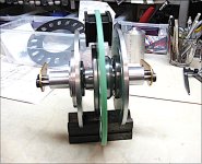
Made a little more progress on the motor. I decided to dismantle the old motor for hardware and parts, since it's just
going on a shelf, and theres no since spending good money twice. As it turns out, the bearing's and caps are exactly the
same dimensions as I need for this motor, so it saves me a lot of time and work to reuse them.

I ordered up a couple of 6" aluminum discs from the Bay, and turned them for the bearing and back iron ID'S, then drilled
them for air inlet holes. I plan on chamfering the holes on one side of the hole, both inside and out, so that they will
scoop air in as it spins, and the outer fans will pull it out. Hopefully this time we'll get some real air flow going on.


V2 Hub assembly .jpg

Now it's on to the steel rotors, and spacers. :thumb:
 
APL said:
Well, we'll get back to that later, I have a lot of research to do on back iron thickness. It depends on so many things,
magnet thickness & T value, delivered current, magnet spacing, and air gap.
For now I'll just stick with adding steel rings to the outside, and checking performance.

If there is no flux leakage then you have sufficient back iron. You could find it out by yourself if you put two or more magnets side by side on a steel plate with given thickenss and check for leakage on the plate with a paper clip for instance.
Any leakage will darate your magnets strength.

Have you thought about going with 20P instead of 16P? In case you wanna reduce weight this would be helpful.
 
Thats a good idea, I remember doing that on the last motor, with the paper clip. A small experiment would go a long ways.
Using 20 magnets instead of 16 is a great idea too, it has the same winding factor, and the motor should spin slower than
it would with 16 PM's, which is what I'm after also.

If I use more magnets than slots, then the magnet face width, or pole arc, is smaller than the tooth width. Does that mean
that I need to shorten the tooth width to match the PM's? I'm still a little foggy on the magnet width scenario, and need to
do some research on it before I get that far.

It seems like, from what I've seen so far, that the pole magnet can be as wide as you want, with no separation, filling the
diameter,.. but never smaller than the tooth face.

 
After looking around a bit online, I see that I was wrong about pole magnets being no wider than tooth width. They can
indeed be smaller,.. much smaller. I need to do some studying on motor geometry, and the relationship between the
tooth and pole sizes. Problem is, I'm not finding that much yet, probably because I'm not phrasing the question right .
 
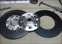
I was able to chamfer the air holes in the hub flanges, to create a sort of turbo fan, and help draw in air as it spins. They
only work in one direction, but that will be fine for this bike. It also makes the original hole area much larger overall.
Hope I didn't just create a whistle!

I have a friend with a body shop that has a CNC plasma torch, and was kind enough to cut me some soft steel rings close
to the size needed for the rotors. I left a little extra material on them so that they could be turned down to the exact
size, and make sure that the inside and outside are perfectly parallel with each other.

One rotor is mostly done, and it turned out super nice,..fits the inside lip that was turned into the hub perfectly. This motor
is going to spin laser straight! :thumb:
A lot of holes are going to be drilled around the outer edge, where the spacers go, and should lighten it up a bit. There will
be more holes drilled on the inner diameter, to be riveted to the hub, but I need to bond the magnets first, and then drill in
between them.

Hub fans and rotors..jpg
 
What other saving or exporting options do you have in your CAD software? I'd be surprised if there's no way of converting to a more exact format than STL but that may be their funding model :/ Just a point on those air vents, can fingers get caught in them? Just mentioning it because I once nearly took a finger off on one of those wavy brake disks, damn things are like a guillotine!
 
Lots of headaches in trying to find the proper pole arc,  (magnet width),  for these magnets.  It doesn't look like theres
going to be any simple explanation, or formula, and I'm finding out that this 'one simple thing' is tied into cogging torque,
torque ripple, air gap flux density/ leakage, and magnet end leakages,and the entire torque, and motor efficiency is
affected by it.

I don't have it quite figured out yet, but heres some of what I've found so far.

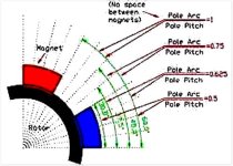
Pole pitch, is the largest width that a magnet can take up.  On this motor, if I place 16 pole magnets around the back iron
end to end so that they touch, that would be the pole pitch of each magnet.
Pole arc, is the actual width of the magnet. 
It's usually, (but not always),  smaller than the pole pitch,.. leaving spaces between the magnets.  The difference between
the size of the arc and pitch is called the 'pole pitch to pole arc ratio'.
This ratio is what were after,  and is usually expressed in fractions of 1,.. like ,25, .05, .75, .9, or 1, and so on. 
It can also be expressed in radial degrees.

Two ways to show ratio;
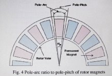
IMG_2164 copy 2.jpg
Pitch and Arc ratio. copy.jpg

A motor has 180 electrical degrees, and 360 mechanical degrees.  So the 180 electrical degrees are what we use.  A pitch
that takes up 30 degrees would be expressed as 30/180.
'Coil' pitch and arc are done the same way.

Obviously, the larger the ratio,,, say, one to one, where the arc and pitch are the same size,., or the magnet is as wide as
it can possibly be,.. the more torque a motor will have.   But it may lead to excessive cogging torque, and ripple.
One of the main reasons for having a little smaller ratio, is to find the ratio that causes the least amount of cogging torque,
which is a bad thing for motors, as it leads to inefficiency's and noise.  Other things to adjust ratio's for, are torque ripple
and flux leakage, which also need to be taken into account, to attain the most perfect ratio number.
The ratio is always a bit of a compromise.

I'm don't really think I need the 'perfect' ratio at this point,.. I'm more or less after a good average number that will do the job.  Finding the perfect ratio requires computer programs and calculations beyond my abilities for now.

It's a little too early to tell, and I have a lot of studying to do yet, but at the moment that number seems to be around .75,
or a magnet about 3/4 the size of the pitch. That would leave a 1/8 gap on either side of a pole magnet.
Lots of info to go through yet.
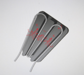
 
Stan.distortion, It's a simple CAD program, and yea, theres an optional app. for STEP export, but it's expensive. $500.
Bikes are dangerous indeed, we all learn early on about chains. :shock: and front wheel spokes and forks.
Now it's brake discs, (believe me I know!!), and moving on to motors and batteries. Lucky we have any fingers left!
 
I'm sure there's some fancy math for all of the magnet spacing stuff, but based on observation, the gap can be anywhere from zero to about the thickness of the magnets and it will make virtually no difference. In other words, don't worry about it too much.
 
Back
Top