APL's DIY axial-flux motor

I haven't snapped to many yet, but I scored these all the way around, and they didn't take any effort to snap at all,
clean and straight too. Of course, I have a lot to brake yet,.. so I'll have to wait and see...

Keeping the magnets straight, N and S, is going to be a little hard, for sure. Plus, I have to mirror them N and S on each
back iron, which will be hard as well. I'll mark them with a sharpie, but it would nice if they were bonded as a one pice
trapezoid before they get bonded to the back iron.
I thought about bonding a piece of .020" fiberglass board to the outer face, and bonding the segments together vertical
at the same time. Maybe even slide a piece of paper or mylar in between the segments for some separation.
It would make it easier to sand/prep the backsides before bonding too.

Problem is when I go to bond them to the back iron if they're in one piece,.. will they brake apart when I get them close
to the steel? .020" board is not very stiff. Can I drop them in the spacer in one quick move? I Maybe could slide them on,
.. but might push all the glue out of the way. :?:
 
When I did my tiling job, I glued one segment first. Once that cured I used it as an anchor to pull the other ones against. Dropping the magnets onto the spot can be messy. The glue can shoot out around the sides. Sliding them on is probably better. Just butter both faces with glue first and have something handy to wipe up the excess. You don't need much glue if the faces are really flat.

You should practice on a piece of scrap back iron.
 
Good idea doing one row of segments first, makes getting everything lined up and the correct orientation easier, and
lock's it down. Easy to check everything once they're dry, and possibly change something if needed too.
It's going to take some thought, and a little practice for sure.

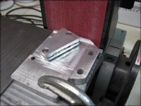
I managed to make the sanding fixture out of some aluminum scrap, today. I milled stop's on the base, and another on
the sander, so it can only move so far towards the belt. I could have 3D printed it, but I think this will be more durable,
and will draw heat away better.

It worked pretty good on the first test,.. not perfect, but good enough. I can only get better. I'll move the set up outside
and wear a paint mask once I get going,.. I wouldn't want to breath that stuff, whatever it is.

And so begins, the million magnet grind. This is going to take a while. :(

Magnet sanding fixture..jpg
 
Make sure the magnets don't get hot during sanding. I've seen them get pretty badly demagnetized doing that. Wet sand if possible.
The aluminum is good as it will act like a heat sink.

A small gaussmeter is a really handy thing for this kind of work. One that won't saturate with your magnets. It may be possible to build a cheap one using a hall senor and a voltmeter.
 
I'll have to keep an eye on that. I can feel some heat while sanding, and switch sides often, but it may still be robbing
some magnetism. I'll try dipping it in water often too.
These things are extremely strong though, and I can probably stand to loose a smidgen.

Wtuber turned me on to a link for physics phone app's that include a magnetometer, early on in this thread, which I used
with good success. (free)
I also looked at buying a calibrated one, but they are not so cheap. You can make one as well, but the phone will
be much better. It isn't all that accurate numbers wise, but shows relative differences very well, which is all that I need.

I'll have to dust it off, and see if I can get it going again. It would be good to know early on, what kind of damage I'm doing.

https://www.vieyrasoftware.net

Mgnometer App..jpg
 
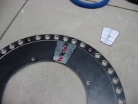
I had a rude awakening when I realized that the segments were aligning north and south. I had assumed that they would
naturally align all N on one side and S on the other, just like any other trapezoid. Now I see what you mean when you say
they don't want to go together. Thought you meant the whole pole magnets.

They really don't want to go together, theres a lot of force there keeping them separated! It just doesn't seem right to force
them together.

Thats going to make it much harder to bond them than I thought. The only way I can see to do it, is to bond one row of
segments at a time, around the diameter, like you were saying, and do all four rows, one row at a time.


Segment orientation..jpg
 
Not only does it take a lot of force to push them together, they also have a strong tendency to flip over so you may need to clamp it against the back iron as well as force it into position against the first magnet. I'll try to find a picture of my old jig, but I'm sure there is a better way to do it. Basically a pair of wooden wedges that push the magnets together and a block of wood to push against.

Once you put glue on them, they really slide around too and a flip over accident gets really messy.

I'm trying to think if a 3D printed form of some sort would work.
 
APL it is nice to see you are taking the effort with segmentation, but braking magnets into pieces and sand them to shape sounds like troubles with debries and the dust is known to be unhealthful.
I understand that you wanna do as much DIY as possible, but i have the opinion that one should not overdue it here.

Have you ever asked a magnet supplier for a quotation? I bought custom magnets a few times now and was surprised how cheap that was, or at least not much more expensive as those standard size stock items. You also could choose the type of coating, like black epoxy which should further improve losses since it is non-conductive :wink:

edit:

APL said:
Thats going to make it much harder to bond them than I thought. The only way I can see to do it, is to bond one row of
segments at a time, around the diameter, like you were saying, and do all four rows, one row at a time.

:thumb: thats exactly how i would do. The outer row i would glue with epoxy and all the other with Loctite 438.

Epoxy will give you the time it will take to place and align the magnets on the plate.
Let it dry a bit, remove excess glue (on the one side where the next magnet will be glued to it) and then let it harden.
For the remaining segments i would use Loctite 438 because it will dry quick which is something you will like when pressing the magnets together. Some seconds should be enough so it should be doable without a jig (which anyway sounds like some additional hours of work).

Don't forget to sand the surfaces and clean them. Your back iron looks like "raw steel" which probably will not give you good results. The preparation of bonding surfaces is of significant importance for the bonding strength.

Do you make 20p or 16p now?
 
I can't think of anything 3d printed that' going to help you much with glueing the magnets down, a guide to locate in the holes around the circumference and maybe a vice jaw to push the magnets together once they're laid flat but the glue will make it a pain to get apart afterwards. Maybe wax on the jig surface would help with that but I wouldn't like to risk oil, silicone spray etc. To easy for it to effect the bond between the magnets and rotor.

I was planning to enclose the magnets and rotor in a 3d printed casing here, it means an extra 0.5mm or so between the rotor and stator faces but should be an extra support in addition to bonding and help with alignment/assembly and wind drag/noise. Not sure it would be any help with stacked magnets though, they'd probably be an even bigger pain in the ass to get into the support than onto the rotor!

Are they easier to push together on the rotor than in free space? Something's telling me it should work that way and some small ones I have here seem easier but it might just be the extra friction, could be sandwiching them between the rotor and another steel plate may help.
 
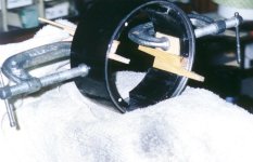
Below is a picture of a magnet tiling project on a radial motor (from 2001). The C-clamp keeps the magnet from flipping over. The wedges were used to push the segments together. This motor was still working as of about a year ago and is in my original Zappy scooter now used by the SF Giants mascot.

MAG4.jpg

If the wedges were made out of polypropylene or polyethylene, they won't stick to epoxy. I only used wood since it was handy.

I'm pretty sure you will need to both hold the segment down against the back iron and push it against the neighboring segment. If you're lucky, the attraction to the back iron will be enough to keep it from flipping over and you can just push it against the neighbor.

I used very slow epoxy, the 2 hour kind. This gives enough time to mix thoroughly and get the magnets positioned before it starts to set. The slower setting types tend to be stronger also. I agree the surface prep is important. I had failures in the past from traces of oil on the surface. Sanding and cleaning with alcohol worked well.

So the trick will be to make a holding jig that's easy to duplicate so you can do more than one magnet at a time. You might be able to machine something out of plastic or aluminum.

You may be able to make something that sort of resembles a C-clamp but flat and wide that goes over the magnet and has a screw that pushes on the outside edge of the rotor. The force needed to push the magnet segments together isn't extreme but the glue takes away any friction on the back iron so you need to confine it with clamps.
 
Well, it's good to know that I didn't have a brain fart, and get the wrong magnets or something. I just wasn't ready for
the repulsion thing. Still boggles my brain. I was hoping that the attraction to the back iron would diminish the effect
stan,distortion, but it only helps slightly. I can just barely push them together with my fingers, and really need a clamp.
A thicker back iron, and mill some shallow pockets into it, is probably the answer to the spacing part anyway.

I decided to go with the 16P madin88, even though 20P is a better idea, and gives more torque and slower speed with
less back iron. You are certainly right about that.
I checked the back iron with a paper clip, and there was no attraction. 16P is a little bit easier, and at the moment,
I'm thankful for that. I guess I'm still struggling with it,.. which way to go. It's still on the table.

I will look into having magnets made, but I'd like to be sure that this is all going to work first. It would certainly be worth
something not too have to go through the bonding issues were talking about now. Right again.

The magnets are bought, and I'll try to see it through, but might find out differently yet. It's at least worth the experience.
I'll keep struggling with this set up for a while,.. and customs aren't out of the picture yet.

I plan to prep the steel and magnets before bonding, just haven't got that far yet. I looked around a bit , but Loctite 438
isn't that common here, for some reason. I think I'll do the slow cure thing anyway,..and just clamp things down.

Fechter, it's good to know polypropylene won't stick, even wood wouldn't be so bad, as it can be sanded off easily,.. is
there a 3D material that won't stick? Otherwise, I was thinking of leaving the inner spokes bonded, and cutting the
inner and outer rings off the spacer once it dries. The spokes will only be 4mm wide or so.
I could probably just use 4mm 'stick' spacers, as well, but would feel more comfortable having the rings connect them.

Thanks for all the help guys, this is an unexpected hurtle, and I need the ideas.
 
After thinking about it some more, I think a good plan would be to 3D the spacer, and then glue the bottom and top
magnets in first, since they will be far enough apart as to not affect each other,.. place a small spacer in between them to
make sure the inside magnets will fit. There won't be any stress on the spacer, or the magnets at this point.

Then, after they've dried, it's just a matter of squeezing the other two magnets in between the first ones, and clamping
them down. They will be located in all directions.
Easier said than done. :wink:
 
Get one thing figured out, and another pops up. Fechter was right about grinding magnets,.. it does diminish their power.
But I'm not sure whats doing the damage,.. when I took the temperature immediately after grinding, it was never above
70 degrees. So maybe the vibration, along with momentary heat. :?:

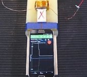
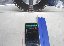
I found the phone with the meter app on it, and set up a small experiment to test the difference between snapped, ground,
and stock magnets. I had to make sure the phone didn't twist sideways, as it changes the readings a lot.

I moved the phone until it read about 350 on the scale. (it saturates at 1200) Both the stock, and the snapped magnets,
were in the same spot. But I had to move the phone about 55mm forward to get 350 for the ground ones.
Or, when read from the same spot, 350 vs 120.

So, it seems that it's OK to snap, but not to grind. Looks like I'm going back to the 20P idea, for shorter magnets, since I'll
need to cut both sides. And customs are looking more, and more likely. We'll see what today brings.

Magnometer test. V2.jpg
 
I'm pretty sure it's the heat from grinding. It may stay cool enough on the surface but maybe not in the middle. I can't think of any other reason they get demagnetized, but have seen it happen enough times.

I was going to try using a tile saw that uses a diamond blade and is water cooled, but switched projects before I got there. You can rent them from tool rental places or for about the same price get a cheap one from Harbor Freight. No idea if it will work and the blade is magnetic so may be quite challenging.

One trick that you can use on your axial rotor that I couldn't use on my radial design is to place a large magnet on the back side of the iron in the same direction as the ones getting glued. If the magnet is big enough, it will mostly saturate the iron and the tiles won't have so much tendency to flip over. It will also reduce the repulsion between tiles as some of their flux will now be going to the big magnet.

Also, when gluing, avoid placing the magnets over the spot and dropping them on. They will attract the iron and the force will be enough to shoot any excess epoxy out the sides with considerable force (huge mess). The clamping force is great for glue jobs, but you just need a way to slowly position the magnets so they don't suddenly snap into place. It generally works to slide the magnets into position. You can sometimes use a non-magnetic wedge between the magnet and iron for initial positioning then slowly slide the wedge out.
 
APL said:
Get one thing figured out, and another pops up. Fechter was right about grinding magnets,.. it does diminish their power.
But I'm not sure whats doing the damage,.. when I took the temperature immediately after grinding, it was never above
70 degrees. So maybe the vibration, along with momentary heat. :?:
Which grade they are?
If you work with a magnet which is rated for 180°C for example, it means that it can withstand this temparature only in a closed magnetic circuit with 100% return.
The magnet alone in free air will loose strength already at lower temps.
And customs are looking more, and more likely. We'll see what today brings.
Well, why don't you just ask?
 
I learn things by experimenting, and trying to solve problems. Just buying our way out yields little knowledge. I've learned
a lot in the last few days,.. mostly not to try to do this. :lol:
It would be a feather in my cap if I can make my own magnets, so I'll keep trying for a while, wouldn't want to give up too
easily. I have a few things to try.

As stated before, N52's aren't the best magnets to be working for this, and are probably lending to the problem.

Fechter, I was going to try the water cooled tile cutter idea, I have a buddy with a few of them, but after looking at them,
I'm a bit skeptical. The blades are not that thin, and make a fairly wide cut, and holding the magnet somehow is not that
easy. Plus, I tried cutting them with a very thin diamond Dremel disc, and they tend to break and crumble, so I don't have
much faith in it. They would be a pain to get set up, but I suppose I should at least try one. I'm still kicking it around.
I think if I just practice scoring them better I'll have good luck.

Good idea to use a large magnet on the backside, I'll try that. The middle ones are really going to put up a fight!
 
APL said:
I learn things by experimenting, and trying to solve problems. Just buying our way out yields little knowledge. I've learned
a lot in the last few days,.. mostly not to try to do this. :lol:

It's also very entertaining to follow along in this thread :thumb:

Very cool.
 
APL said:
As stated before, N52's aren't the best magnets to be working for this, and are probably lending to the problem.
Then 80°C
With those you get automatic field weakening when the motor heats up
More heat = more speed :mrgreen:
 
Are you sure they've weakened by that much, if you've cut one in half wouldn't you end up with 2 magnets with half the strength? I'm not sure where would be the best place to measure their strength from too, if you pointed a hall sensor in the direction your phone is pointing in the picture it wouldn't pick up a strong field, the lines of flux would be travelling around it in all directions rather than through it. I'm guessing the phone uses the compass so it would just need to be on the same plane to point north but it's something that's caught me out with hall sensors before.

I'd used a sharp chisel to split neodymium magnets before and it seemed to work well, it cut cleanly and easily for the few I did but the shock probably didn't do them any good. Maybe the same approach with a steady force would work, a garden shear or bolt croppers? When you said filing them smooth it seemed like the best approach to me too, grinding may be too aggressive and I wouldn't like to guess at what health hazards are in the dust.
 
Thanks for the support! It'll work, maybe not the best, but I'll be rollin down the road,.. and improvements can always be
made. I think this motors going to rock! :)

I'm more interested in finding a motor platform thats relatively easy to make, and move out from there. The ES is about
information, and helping others, so I try to include as much as I can here, and your help and info. is a big part of that. :thumb:
The art of torturing magnets is a good subject.

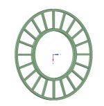
Heres the proposed PM spacer. Theres a lip on the inside diameter to fit inside the back iron hole. The spokes might be a
bit weak, so I'll probably have to bond them to the steel first, and cut the rings off after the PM's are glued in place.
The spokes between the magnets are 4mm, giving me 1mm or so to remove some plastic for fitting magnets if necessary,
the edges will be a little rough.

PM spacer 1.jpg

I couldn't find an easy way to put flats on the rings for the magnets, but I think this will work in my favor anyway, to keep
glue off the rings.
 
Shop-time has been scarce lately. But the spacer rings are being printed, and I don't want to make too many magnets
without them, to make sure of the fitment.
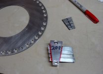
So I've been making simple fixtures to make the process easier, and practicing the technique. I remade the aluminum
holder for 20P, and just use it to mark them with a sharpie. Then they get scored in another, steel, fixture.
I've also been sanding the rotors in prep for bonding. The black oxide coating is not very easy to remove.

20P marking fixture..jpg

I've been having real good luck using a Dremel composite cut-off disc to score them, and it doesn't make very much dust.
I still use a 'cartridge' paint mask though, to be safe.
It turns out that the small edge side of the magnets needs to be scored the most, in order to get a good clean snap.
At least, on these long narrow magnets,.. other magnets and shapes will probably be different.
Using the magnometer on the new versions, I'm not getting much of a loss, so I think this is going to work. A lot of elbow
grease though, and I'm sure not very inclined to do it this way again.

Anyway, at least for this motor, we can move forward. :thumb:
 
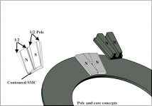
Back to these guys again,.. I keep rolling ideas along for using simple magnet shapes. Some of the of the newest ideas
are a dual coil core,.. or concentrated winding, that use same direction poles,.. and multiple SMC contoured back iron
piece's that have 'steps' built into them for the magnets to be bonded into. One section spans two half poles.

Pole and core concepts..png
 
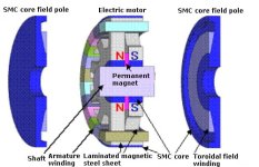
Found this motor the other day, but I haven't deciphered it yet. The side rotors get induced somehow to produce
a resulting magnetic field. The coils fit into the groves in the side poles, and the core fits up against armature.
Not sure how the pink magnet works, or the armature.

The motor is supposed to use very little PM magnet material.

hybrid-field-motor.jpg

From; https://www.greenoptimistic.com/hybrid-field-motor-magnet-20100331/
 
It's a bit confusing, because it doesn't seem to be divided into the usual poles or segments were used to seeing.
At least, they aren't showing any magnetic separations, but there probably is. The picture is pretty basic.
When I look at the coils in back, they appear to be only half wound. :!:

hybrid-field-motor copy 2.jpg

I'm assuming that it's an axial, but maybe I even have that wrong.
 
Back
Top